Show all chapters ▸Hide chapters ▾
- 1Graphics Kernel Anatomy 101
- 2The Cambridge Connection: Foundations of Modern CAD
- 3Proprietary versus Licensed Kernels
- 4Solid Edge versus SolidWorks: Two Different (but similar) Paths to Parasolid
- 5Cautionary Tales in CAD: When Tech Isn’t Enough
- 7The Computational Alchemy: How Graphics Mathematics Forged the AI Age
- 8The Evolution of Surfacing Technologies — People, Companies, and the Creative Machines Behind the Magic
- 9The Evolution of Graphics APIs
- 10How MCAD and Computer Graphics Drove Each Other: A Story of Mutual Acceleration
- 11CAD Wars
- 12CAM Wars: The Machinist's Digital Shadow
- 13CAE Wars: Simulation Eating the Physical World
- 14Cross-Kernel Synergies: The Integration Imperative
- 15The Kernel Wars: A Modern Perspective
Key Takeaways
- Geometric modeling kernel handles solid and surface B-rep geometry
- Part modeling includes parametric features and constraint solvers
- Assembly modeling manages part relationships and kinematics
- Visualization layer converts precise geometry for real-time rendering
- Graphics kernels are modularized with distinct layers
Short Answer
A graphics kernel is essential for CAD systems as it manages 3D model rendering and manipulation with precision. It consists of several layers, each performing specific functions crucial for design efficiency.
- Handles the core geometric modeling operations
- Manages rendering to ensure visual accuracy
- Supports real-time modification of 3D models
- Facilitates efficient data exchange between CAD applications
Why it matters: Understanding the graphics kernel is critical for PLM practitioners to optimize design workflows and enhance product development processes.
What is a Graphics Kernel?
A graphics kernel is the unsung hero of CAD systems, managing the rendering and manipulation of graphical elements. For the formal definitions used across this site, see Geometry Kernel and CAD Kernel in the glossary. It is responsible for handling the fundamental operations required to display and modify 3D models, ensuring precision and efficiency in design processes. The architecture of a graphics kernel is typically layered, with each layer contributing specific functionalities.
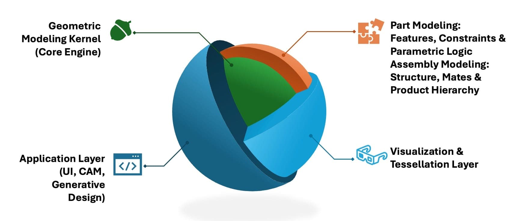
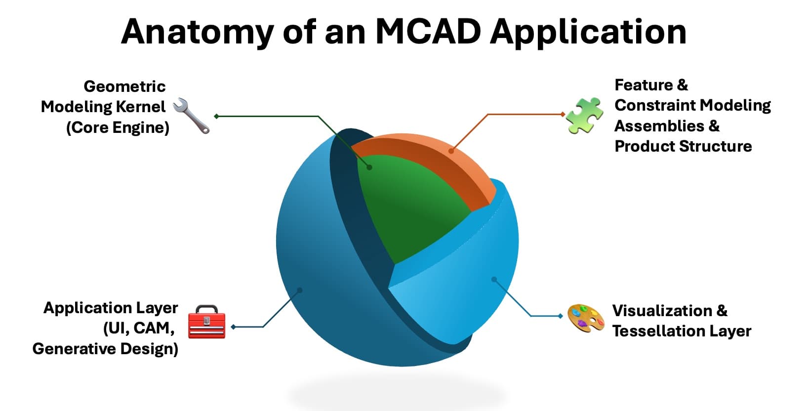
The Layered Architecture of Graphics Kernels
1. Geometric Modeling Kernel (Core Engine)
The geometric modeling kernel is the core component of any 3D CAD system. It performs solid and surface modeling using boundary representation (B-rep) geometry and supports operations like Booleans (union, subtract, intersect).
B-rep, or boundary representation, is a method for defining 3D geometry by its surfaces, edges, and vertices—allowing for precise control over complex shapes and topology. It is the foundation of most modern solid modeling systems.
These kernels also support exact surface representations such as NURBS (Non-Uniform Rational B-Splines), which are a mathematical model for smooth curves and surfaces. NURBS are critical in high-precision design, especially in automotive and aerospace, due to their ability to accurately describe freeform geometry.
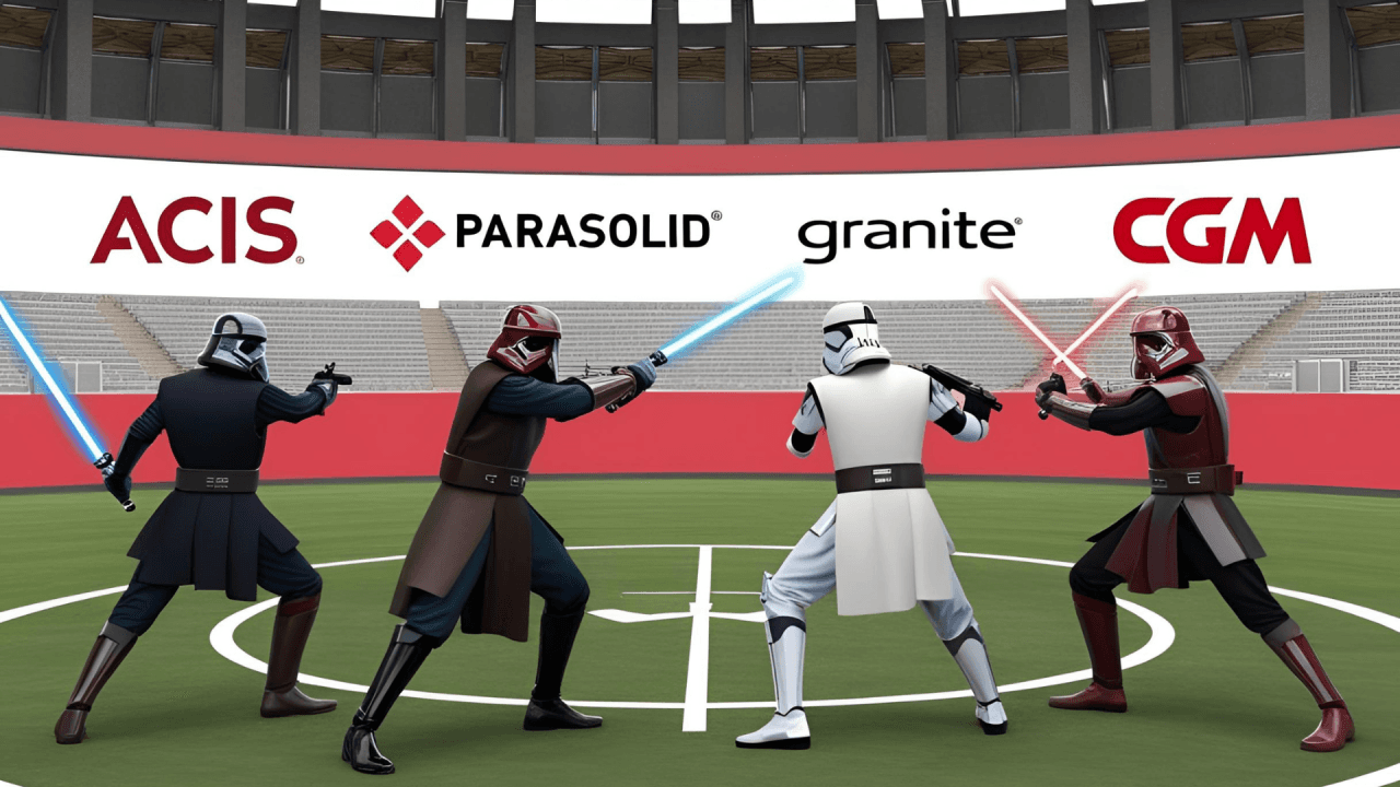
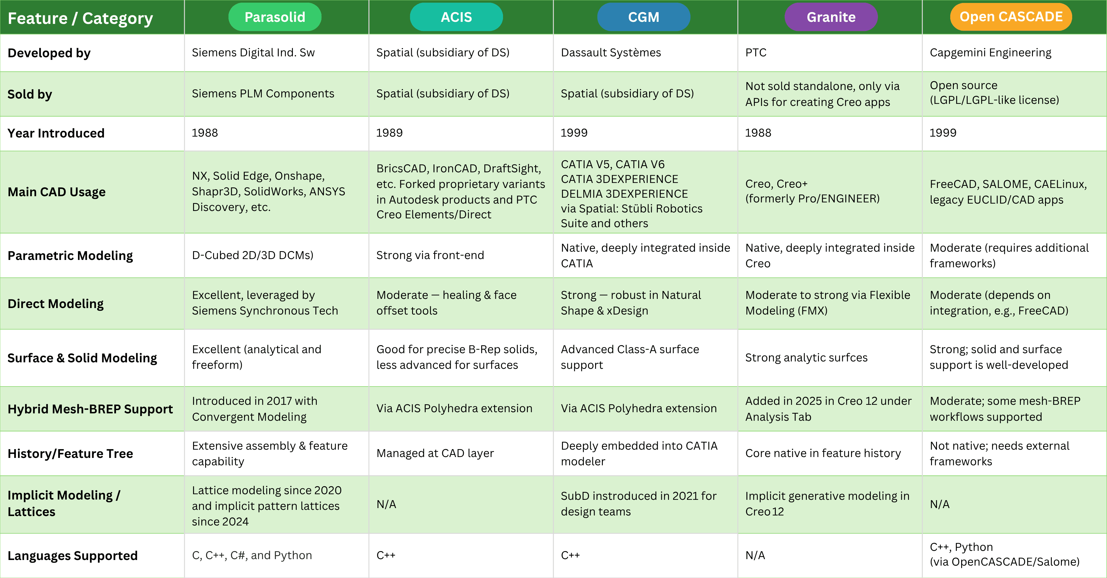
Leading kernels include:
- Parasolid (used in Siemens NX and Solid Edge, DS SolidWorks, PTC Onshape)
- ACIS (used in Autodesk AutoCAD, BricsCAD)
- CGM (used in Dassault Systèmes CATIA V5 and 3DEXPERIENCE)
- Granite (used in PTC Creo)
- ShapeManager (a fork of ACIS used in Autodesk Inventor and Fusion 360)
- SolidDesigner kernel (a fork of ACIS used in PTC Creo Elements/Direct, formerly CoCreate)
The next layer has really two very closely related sub-layers:
2a. Part Modeling: Features, Constraints & Parametric Logic
This sits directly atop the geometric kernel to define and control individual part shapes.
- Adds parametric feature history (extrudes, holes, fillets, etc.) for design replay/editing.
- Defines sketches with geometric and dimensional constraints (e.g., parallel, equal, fixed).
- Enables direct modeling and push-pull interaction where parametrics aren't used.
- Maintains design intent via dimensions and expressions (e.g., hole_diameter = 2 * pin_radius).
- Uses constraint solvers (e.g., Siemens D-Cubed 2D/3D DCM and Spatial's CDM) for solving geometry relationships.
- Provides topological tracking to maintain stability across edits.
2b. Assembly Modeling: Structure, Mates & Product Hierarchy
This one operates at the multi-part product level to manage relationships, structure, and motion.
- Supports mating conditions (coincidence, tangency, angle, distance) between parts.
- Enables kinematics and motion simulation of assemblies with moving components.
- Tracks instance relationships, part reuse, and subassembly structure.
- Builds the product BOM hierarchy (Bill of Materials).
- Supports lightweight geometry and interference detection for large assemblies.
- Handles spatial organization and positioning of parts in 3D space.
🔍 Why this matters:
This separation reflects how CAD software is typically modularized internally:
- The part modeling engine is usually focused on feature trees and constraint solving.
- The assembly engine is often a distinct module handling spatial logic and performance at scale.
3. Visualization & Tessellation Layer
- Converts precise geometry into displayable triangular meshes for real-time 3D views.
- Interfaces with graphics engines (e.g., OpenGL, HOOPS) for shading, zoom, and rendering.
- Ensures fast viewport performance without compromising underlying accuracy.
4. The Application Layer: Where Innovation Meets the Engineer
If the geometry kernel is the beating mathematical heart of CAD, then the application layer is its visible face—the part users actually see, touch, and use to bring their ideas to life. This is where the abstract becomes tangible, where parametric models, direct editing, and digital threads are made accessible through intuitive interfaces and powerful workflows.
It's here you'll find your favorite MCAD tools and familiar user interfaces. Every time you sketch a profile, extrude a solid, or fine-tune a feature, you're interacting with this layer—sending instructions down to the kernel, which quietly handles the mathematical heavy lifting. The application layer is also home to advanced modules for CAM (generating toolpaths for CNC machining), automated assemblies, and cutting-edge generative design workflows. When you use generative design, AI-driven algorithms repeatedly query the kernel, exploring thousands of possible solutions in minutes—something unthinkable in the days of manual drafting.
But What About Meshing?
To simulate, test, or optimize a design, engineers turn to FEM/FEA (Finite-Element Meshing/Analysis) tools. Meshing is the process of breaking complex 3D models into smaller, solvable elements—a crucial step for simulations, from crash tests to thermal analysis.
Here's why this matters:
- Meshing tools often straddle the application and kernel layers.
- For high-fidelity results, they must tessellate (slice up) the exact geometry produced by the kernel.
- This means robust integration with kernel APIs is essential for accuracy and reliability.
You'll see meshing as part of the application layer in popular simulation modules like SolidWorks Simulation or Creo Simulate—but behind the scenes, these tools are deeply reliant on the underlying geometry engine. The tighter the integration, the better the analysis.
Real-World Applications
Each kernel serves distinct strengths in real-world MCAD workflows.
- Parasolid, known for its robust Boolean operations and stability, excels in complex assemblies and history-based modeling.
- ACIS, with its flexible licensing, is favored in mid-tier CAD and direct modelers.
- CGM, tightly integrated into Dassault Systèmes' platform, supports high-precision surfacing and multi-discipline integration, ideal for aerospace and automotive engineering and design.
- Granite, developed by PTC, is optimized for parametric associativity and interoperability.
Whether for simulation-ready meshing, generative design, or downstream CAM, modern MCAD systems rely on these kernels as silent engines—translating design intent into precise, editable, and manufacturable 3D geometry.
Want to listen instead of read? 56 DemystifyingPLM articles are available as audio.
Browse audio →Show all chapters ▸Hide chapters ▾
- 1Graphics Kernel Anatomy 101
- 2The Cambridge Connection: Foundations of Modern CAD
- 3Proprietary versus Licensed Kernels
- 4Solid Edge versus SolidWorks: Two Different (but similar) Paths to Parasolid
- 5Cautionary Tales in CAD: When Tech Isn’t Enough
- 7The Computational Alchemy: How Graphics Mathematics Forged the AI Age
- 8The Evolution of Surfacing Technologies — People, Companies, and the Creative Machines Behind the Magic
- 9The Evolution of Graphics APIs
- 10How MCAD and Computer Graphics Drove Each Other: A Story of Mutual Acceleration
- 11CAD Wars
- 12CAM Wars: The Machinist's Digital Shadow
- 13CAE Wars: Simulation Eating the Physical World
- 14Cross-Kernel Synergies: The Integration Imperative
- 15The Kernel Wars: A Modern Perspective
Looking up PLM terminology? Browse the canonical reference.
PLM Glossary →Cite this article
Finocchiaro, Michael. “Chapter 1: Graphics Kernel Anatomy 101.” DemystifyingPLM, June 12, 2025, https://www.demystifyingplm.com/chapter-1-graphics-kernel-anatomy-101
PLM industry analyst · 35+ years at IBM, HP, PTC, Dassault Systèmes
Firsthand knowledge of the evolution from early 3D modeling kernels to today's cloud-native platforms and agentic AI — the history, strategy, and future of PLM.