Key Takeaways
- SubD models start with simple polygons and refine through weighted averages.
- Catmull–Clark, Doo–Sabin, and Loop schemes define SubD surface rules.
- SubD offers topological freedom and curvature smoothness over NURBS.
- Modern CAD tools blend SubD for free-form design with NURBS for precision.
- SubD is ideal for organic forms in mechanical engineering.
🎧 Audio Version
Listen to "From Polygons to Perfection: The Math and Engineering Power of SubD Modeling"
More audio articles at DemystifyingPLM/listen
Short Answer
SubD modeling uses a mathematical technique to create smooth surfaces from simple polygonal meshes, allowing for more organic and complex shapes in design. It bridges the gap between low-poly efficiency and high-poly detail, enabling designers to work with editable smooth models.
- SubD allows for the creation of smooth surfaces from polygons
- It supports both efficient low-poly modeling and detailed high-poly designs
- SubD is used in various industries including automotive and medical devices
- It enhances design flexibility and precision in PLM systems
Why it matters: For PLM practitioners, SubD modeling improves the accuracy and efficiency of product development by enabling more realistic and complex designs while maintaining manageable file sizes.
A funny thing happens when you zoom out far enough on the history of CAD:
every few decades, the mathematics behind geometry quietly change — and suddenly, an entirely new design vocabulary opens up.
The 1980s brought solids and Booleans.
The 1990s perfected NURBS and parametrics.
And the 2020s? They might belong to fields and SubD.
Subdivision Surface modeling — or SubD — is one of those rare ideas that bridges art and engineering.
It started in animation, but it’s now reshaping how we model everything from turbine blades to prosthetics.
Let’s explore the math behind SubD, how it differs from traditional CAD surfaces, and why engineers are increasingly reaching for it in their workflows.
1. The Geometry Behind the Magic
A SubD surface begins life as a simple polygonal mesh — usually quads — and becomes smoother through a recursive refinement process.
Each iteration adds new vertices and repositions existing ones using weighted averages of their neighbors.
That’s the whole trick.
No trimming, no Boolean nightmares, no fragile parameterization. Just pure geometric recursion.
The most common schemes are:
- Catmull–Clark (1978) — for quadrilateral meshes, C^2 continuous almost everywhere.
- Doo–Sabin (1978) — a generalization for more arbitrary topologies.
- Loop (1987) — optimized for triangular meshes.
Each scheme defines a subdivision rule:
take a polygon mesh, split its faces, then reposition points based on a smoothness function.
For Catmull–Clark, the vertex update rule looks like this for P, the new vertex positon:
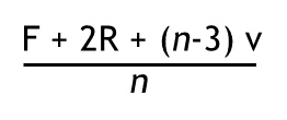
Where:
- P’ = new vertex position,
- F = average of face points,
- E = average of edge midpoints,
- R = original vertex position,
- n = number of connected faces (the valence).
🧮 SubD surfaces converge mathematically to a smooth limit surface as the number of refinement steps approaches infinity.
In other words: the more you subdivide, the smoother and more continuous the surface becomes — without ever introducing parametric seams.
2. How SubD Differs from NURBS and Solids
Most mechanical engineers grew up in a world of B-reps — boundary representations built from NURBS patches. They’re perfect for precision machining, but notoriously rigid when you want free-form flow.
SubD flips that mindset. It trades analytic precision for topological freedom and curvature smoothness.
Feature | NURBS / Solids | SubD |
|---|---|---|
Continuity | Exact C2 across trimmed patches | Approx. C2, except at extraordinary vertices |
Topology | Rectangular (u,v grid) | Arbitrary polygonal |
Precision | Analytic | Approximation via averaging |
Editing | Patch operations | Mesh vertex manipulation |
Conversion | Topologically constrained | Flexible and local |
Use cases | Machined parts | Organic, ergonomic forms |
What makes this interesting for CAD is that modern tools now blend both worlds.
You can sculpt freely in SubD and then convert to NURBS for downstream processes — manufacturing, simulation, or metrology.
Example platforms:
- Fusion 360 Form Workspace (T-Splines)
- Rhino 7 + Grasshopper SubD
- Siemens NX X Convergent Modeling
- Autodesk Alias SubD tools
3. From Pixar to Product Design
Subdivision modeling was born at Pixar, not in a CAD lab.
In the late 1970s and early 80s, Ed Catmull and Jim Clark wanted a way to make computer characters deform smoothly. Their method — Catmull–Clark subdivision — became the foundation of film-grade animation geometry.
Fast forward to today, and that same mathematics drives high-end product design.
SubD is now used in:
- Automotive exteriors and interiors
- Consumer electronics (ergonomic shells and grips)
- Aerospace fairings and drone housings
- Footwear and medical devices
What started as a way to make Nemo’s fins flow is now helping engineers sculpt wind tunnels, design prosthetics, and optimize aerodynamics.
4. Engineering Applications
Here’s where SubD modeling starts to shine beyond aesthetics:
a. Ergonomic and Aesthetic Design
Industrial designers can shape “beauty surfaces” — flowing transitions, soft blends, and organic curvature — without patchwork NURBS gymnastics.
b. Concept-to-Manufacture Pipelines
You can model freely in SubD, then convert to NURBS or solids later for detailed mechanical design. This keeps creativity high early on and precision high at the end.
c. Reverse Engineering
Scanned data and meshes are messy by nature. SubD wraps smooth surfaces around them — a powerful technique for medical devices, restorations, and custom parts.
d. Generative Design and Optimization
Topology optimization produces irregular meshes that defy traditional parameterization. SubD handles them gracefully, maintaining continuity where NURBS would tear.
e. Simulation and CFD
SubD’s curvature continuity improves mesh quality for aerodynamic or structural analysis, reducing numerical noise at patch boundaries.
5. The Math in Motion
Subdivision surfaces guarantee limit continuity — meaning the geometry converges toward a smooth shape as subdivision levels increase.
At regular vertices (valence = 4 for quads), Catmull–Clark achieves full C2 continuity.
At extraordinary vertices (valence ≠ 4), continuity drops to C1 — still smooth enough for most engineering use cases.
The behavior of the surface can be described by eigenvalues of a subdivision matrix S:
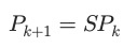
Repeated application of S smooths the geometry, while the dominant eigenvectors define the surface’s limit shape. This stability is why SubD works so well in deformation, sculpting, and simulation — small local changes converge predictably.
“Subdivision is a language of form — continuous, adaptable, and intuitively mathematical.”
6. The Future: Convergent and Hybrid Modeling
We’re now entering an era of convergent modeling, where SubD, B-rep, and even field-based (implicit) modeling coexist.
In Siemens NX and Fusion 360, you can already:
- Combine polygonal scans, SubD surfaces, and solids
- Apply fillets or offsets directly to SubD geometry
- Integrate SubD forms into generative design workflows
And in research labs, hybrid kernels are emerging — mixing subdivision math with implicit fields and differential geometry to produce truly unified modeling systems.
SubD’s flexibility makes it a cornerstone of this new paradigm: it’s mathematically stable, artist-friendly, and engineer-credible.
7. Closing Thoughts
Subdivision modeling is a perfect example of math quietly changing the boundaries of creativity.
Where NURBS gave us precision, SubD gives us flow.
Where solids gave us control, SubD gives us freedom.
And when combined, they unlock something powerful:
a way to design like an artist, refine like an engineer, and manufacture with confidence.
Geometry isn’t static — it evolves.
SubD is proof that even in engineering, smoothness can be a form of intelligence.
Further Reading / Explore More
- Pixar Technical Memo: “Subdivision Surfaces in Character Animation” (Catmull & Clark, 1998)
- Autodesk Fusion 360: Form Workspace Overview
- McNeel Rhino 7: SubD to NURBS Conversion Guide
- Siemens NX: Convergent Modeling Overview
#BetterCallFino #EngineeringSoftwareStartups | #KernelWars | #SubdivisionModeling | #PLM | #CAD
Looking up PLM terminology? Browse the canonical reference.
PLM Glossary →Cite this article
Finocchiaro, Michael. “From Polygons to Perfection: The Math and Engineering Power of SubD Modeling.” DemystifyingPLM, October 21, 2025, https://www.demystifyingplm.com/from-polygons-to-perfection-the-math-and-engineering-power-of-subd-modeling
PLM industry analyst · 35+ years at IBM, HP, PTC, Dassault Systèmes
Firsthand knowledge of the evolution from early 3D modeling kernels to today's cloud-native platforms and agentic AI — the history, strategy, and future of PLM.