Kernel Wars: The Hidden Conflict Behind 3D CAD—and the Hardware That Made AI Possible
What began as a fight to define curves and surfaces in 3D models became the unlikely foundation of the AI revolution.
In the complex, often opaque world of Computer-Aided Design (CAD) software, a quiet but fierce battle has been waged for decades: what I like to call the "kernel wars." This unseen conflict centers on the geometric modeling kernel, the mathematical engine that underpins every CAD system, defining, manipulating, and rendering 3D models. The core strategic divide was whether these powerful kernels should remain proprietary, exclusive to a single MCAD vendor, or be made open and licensable to other Independent Software Vendors (ISVs). While Dassault Systèmes undeniably dominates the high-end CAD market with CATIA and the mid-market with SolidWorks, the underlying kernel market is, without doubt, owned by Siemens' Parasolid. The journey to this outcome is a compelling narrative filled with intriguing side battles—like the direct competition between Solid Edge and SolidWorks—and a rich tapestry of technological innovation spanning mathematics, hardware advancements, API development, evolving methodologies, and graphics libraries.
This silent struggle explains a peculiar phenomenon in the multi-billion-dollar CAD industry: Dassault Systèmes regularly sends a licensing check to its German rival, Siemens for Parasolid. Even PTC, leveraging since its beginnings its own proprietary Granite geometry engine (a name chosen decades after Pro/ENGINEER was released), also quietly licenses Siemens' Parasolid technology for one of its own products. This tangled web of inter-company payments and cross-licensing arrangements is a direct consequence of the strategic decisions and technological prowess that shaped the early days of CAD, particularly in the 1990s when personal computers began to prove their mettle for serious engineering work.
But the impact of these "kernel wars" extends far beyond the CAD industry itself. The insatiable demands of MCAD for increasingly powerful modeling and high-fidelity surfacing hardware directly fueled the development of specialized graphics processing units (GPUs). These very same GPUs, forged in the crucible of 3D design visualization, are now the bedrock of the Artificial Intelligence revolution. Without the relentless pursuit of precision and visual fidelity in CAD, the sophisticated parallel processing capabilities embodied in today's NVIDIA Blackwell architecture, for instance, might never have materialized.
This article delves into the hidden history of geometric modeling kernels, tracing how these essential technologies defined the competitive dynamics and technical capabilities of the MCAD world. It uncovers the profound, often unexpected, consequences of early strategic decisions—decisions that not only determined which CAD software succeeded but also inadvertently laid the groundwork for entirely new technological revolutions.
Graphics Kernel Anatomy 101
What is a Graphics Kernel?
A graphics kernel is the unsung hero of CAD systems, managing the rendering and manipulation of graphical elements. It is responsible for handling the fundamental operations required to display and modify 3D models, ensuring precision and efficiency in design processes. The architecture of a graphics kernel is typically layered, with each layer contributing specific functionalities.
The Layered Architecture of Graphics Kernels
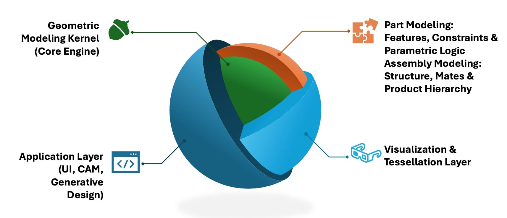
1. Geometric Modeling Kernel (Core Engine)
The geometric modeling kernel is the core component of any 3D CAD system. It performs solid and surface modelingusing boundary representation (B-rep) geometry and supports operations like Booleans (union, subtract, intersect).
B-rep, or boundary representation, is a method for defining 3D geometry by its surfaces, edges, and vertices—allowing for precise control over complex shapes and topology. It is the foundation of most modern solid modeling systems.
These kernels also support exact surface representations such as NURBS (Non-Uniform Rational B-Splines), which are a mathematical model for smooth curves and surfaces. NURBS are critical in high-precision design, especially in automotive and aerospace, due to their ability to accurately describe freeform geometry.
Leading kernels include:
- Parasolid (used in Siemens NX and Solid Edge, DS SolidWorks, PTC Onshape)
- ACIS (used in Autodesk AutoCAD, BricsCAD)
- CGM (used in Dassault Systèmes CATIA V5 and 3DEXPERIENCE)
- Granite (used in PTC Creo)
- ShapeManager (a fork of ACIS used in Autodesk Inventor and Fusion 360)
- SolidDesigner kernel (a fork of ACIS used in PTC Creo Elements/Direct, formerly CoCreate)
The next layer has really two very closely related sub-layers:
2a. Part Modeling: Features, Constraints & Parametric Logic
This sits directly atop the geometric kernel to define and control individual part shapes.
- Adds parametric feature history (extrudes, holes, fillets, etc.) for design replay/editing.
- Defines sketches with geometric and dimensional constraints (e.g., parallel, equal, fixed).
- Enables direct modeling and push-pull interaction where parametrics aren’t used.
- Maintains design intent via dimensions and expressions (e.g., hole_diameter = 2 * pin_radius).
- Uses constraint solvers (e.g., Siemens D-Cubed 2D/3D DCM and Spatial's CDM) for solving geometry relationships.
- Provides topological tracking to maintain stability across edits.
2b. Assembly Modeling: Structure, Mates & Product Hierarchy
This one operates at the multi-part product level to manage relationships, structure, and motion.
- Supports mating conditions (coincidence, tangency, angle, distance) between parts.
- Enables kinematics and motion simulation of assemblies with moving components.
- Tracks instance relationships, part reuse, and subassembly structure.
- Builds the product BOM hierarchy (Bill of Materials).
- Supports lightweight geometry and interference detection for large assemblies.
- Handles spatial organization and positioning of parts in 3D space.
🔍 Why this matters:
This separation reflects how CAD software is typically modularized internally:
- The part modeling engine is usually focused on feature trees and constraint solving.
- The assembly engine is often a distinct module handling spatial logic and performance at scale.
3. Visualization & Tessellation Layer
- Converts precise geometry into displayable triangular meshes for real-time 3D views.
- Interfaces with graphics engines (e.g., OpenGL, HOOPS) for shading, zoom, and rendering.
- Ensures fast viewport performance without compromising underlying accuracy.
4. The Application Layer: Where Innovation Meets the Engineer
If the geometry kernel is the beating mathematical heart of CAD, then the application layer is its visible face—the part users actually see, touch, and use to bring their ideas to life. This is where the abstract becomes tangible, where parametric models, direct editing, and digital threads are made accessible through intuitive interfaces and powerful workflows.
It’s here you’ll find your favorite MCAD tools and familiar user interfaces. Every time you sketch a profile, extrude a solid, or fine-tune a feature, you’re interacting with this layer—sending instructions down to the kernel, which quietly handles the mathematical heavy lifting. The application layer is also home to advanced modules for CAM (generating toolpaths for CNC machining), automated assemblies, and cutting-edge generative design workflows. When you use generative design, AI-driven algorithms repeatedly query the kernel, exploring thousands of possible solutions in minutes—something unthinkable in the days of manual drafting.
But What About Meshing?
To simulate, test, or optimize a design, engineers turn to FEM/FEA (Finite-Element Meshing/Analysis) tools. Meshing is the process of breaking complex 3D models into smaller, solvable elements—a crucial step for simulations, from crash tests to thermal analysis.
Here’s why this matters:
- Meshing tools often straddle the application and kernel layers.
- For high-fidelity results, they must tessellate (slice up) the exact geometry produced by the kernel.
- This means robust integration with kernel APIs is essential for accuracy and reliability.
You’ll see meshing as part of the application layer in popular simulation modules like SolidWorks Simulation or Creo Simulate—but behind the scenes, these tools are deeply reliant on the underlying geometry engine. The tighter the integration, the better the analysis.
Real-World Applications
Each kernel serves distinct strengths in real-world MCAD workflows.
- Parasolid, known for its robust Boolean operations and stability, excels in complex assemblies and history-based modeling.
- ACIS, with its flexible licensing, is favored in mid-tier CAD and direct modelers.
- CGM, tightly integrated into Dassault Systèmes’ platform, supports high-precision surfacing and multi-discipline integration, ideal for aerospace and automotive engineering and design.
- Granite, developed by PTC, is optimized for parametric associativity and interoperability.
Whether for simulation-ready meshing, generative design, or downstream CAM, modern MCAD systems rely on these kernels as silent engines—translating design intent into precise, editable, and manufacturable 3D geometry.
The Cambridge Connection: Foundations of Modern CAD

Before diving into the individual stories of CAD pioneers, it’s worth understanding the deeper technological foundations that shaped the evolution of modern CAD systems. The geometric modeling capabilities behind today’s software can be traced back to foundational research in solid modeling that began in the 1960s, particularly at the University of Cambridge’s Computer Laboratory. Under the direction of Professor Maurice Wilkes, Charles Lang established a CAD research group in 1965 that became a crucible of innovation in computational geometry and computer graphics.
Early breakthroughs emerged with the BUILD boundary representation modeler, developed by Ian Braid starting in 1969 under Lang’s supervision. BUILD tackled challenges in solid modeling—like exact surface-surface intersections—that others avoided through faceting. Alan Grayer joined in 1971, focusing on algorithms for machining prismatic parts modeled in BUILD, leading to one of the earliest integrations of CAD with CAM.
This pioneering work laid the groundwork for ROMULUS, a commercial solid modeling kernel developed at Shape Data Ltd., a company founded in 1974 by Braid, Grayer, Lang, and Peter Veenman. ROMULUS was released commercially in 1978 and became the kernel behind systems like HP’s ME30. In 1985, Shape Data began development of Parasolid as a more advanced successor to ROMULUS, with an improved architecture.
Later that year, Ian Braid, Alan Grayer, and Charles Lang left Shape Data to co-found Three-Space Ltd, collaborating with Spatial Technology Inc., a company founded by Dick Sowar in Colorado. Together, they developed ACIS, a completely new kernel released in 1989, known for its support for both manifold and non-manifold modeling, wires, sheets, and precision modeling techniques. There is a popular story that ACIS' name was derived from its founders, "Alan, Charles, and Ian's System" and there is another that claims they credited the obscure Greek mythology around Acis in Ovid's Metamorphoses. I guess you can choose which one you prefer. Either way, the often-simplified notion that Parasolid and ACIS were developed independently misses the continuity: both kernels trace directly back to the Cambridge team that pioneered boundary representation modeling, and both were led or heavily influenced by the same core individuals.
While Parasolid and ACIS implement similar mathematical principles—such as B-rep, constructive solid geometry (CSG), and separation of geometry from topology—they are distinct codebases. Parasolid was originally written in FORTRAN and C before transitioning to C++, whereas ACIS was developed in C from the outset with object-oriented extensions. Cambridge’s UK legacy in geometric modeling, much like MIT’s in the U.S. PLM scene (see this article) in Cambridge, MA, continues to echo in nearly every major CAD system in use today.
Proprietary versus Licensed Kernels
Let's now take a look at the three primary vendors that own graphics kernels and compare how they either kept them in-house or commercialized then.
PTC Revolutionizes MCAD with Parametric Modeling

Parametric Technology Corporation (PTC) developed its proprietary geometry engine headed by Leonid Raiz (later, one of the creators of Revit) to power its Pro/ENGINEER (now Creo) software, aiming for a robust, in-house solution to support parametric and history-based modeling. It was the world's first fully parametric geometry engine and was an instant success. They ran on UNIX workstations and later Windows PCs, but offered an unprecedented level of flexibility in modeling that changed the ways many products were designed outside the traditional aerospace & defense and automotive niches where PLM had been confined prior to this.

In 2014, PTC started to market APIs for their proprietary geometry engine giving it a name for the first time, Granite. They had hoped to create an eco-system of Creo apps, but they found that it generated little interest on a market more geared towards interoperability. PTC, continues to develop Granite in its Creo products and still allows customers to leverage their APIs to build Creo apps (more on this later in the article).
Siemens Decides to Commercialize Parasolid

By stark contrast, EDS Unigraphics (and later EDS PLM, UGS, Siemens PLM, and Siemens Digital Industries Software) in its various forms and corporate changes) kept to a consisently open framework. Tony Affuso, CEO of this group for over 30 years, told me:
We had a strong belief in our culture that the rich data that customers created with CAD/CAM/CAE (C3) products needed to be shared among many users across their company. If data sharing was successful, it would be extremely valuable to all customers in our industry and would enable the Digital Transformation of their products and their manufacturing processes. You may recall that one of the largest obstacles to data sharing was that C3 vendors all had different proprietary data formats and it was very difficult (not to same occasionally impossible) to convert them into a usable format while maintaining data integrity and modeling history. To help facilitate data sharing between C3 software applications in the 90’s, we created the Toolkit Group whose mission was to build a “the level playing field” for all of the licensees of our Parasolid kernel (and later, the other key kernels from D-Cubed (parametric constraints) and Vistagy (composites modeling)). The Toolkit Group was run as a separate business unit (now called Siemens PLM Components) that worked with all of our competitors using our kernels to ensure equal treatment in kernel technology upgrades and licensing schemes. Our belief was that the kernels were more of a commodity and that the competitive differentiation for software app developers was really the application on top of the kernels. As time has gone by, the teams & management involved with running “the level playing field” at UGS and later Siemens have licensed these toolkits to well over 200 software vendors and have achieved remarkable results in the enabling the rich data sharing for C3 customers across the globe.
This was really a turning point in the industry and we will see later than there are still many competitors to Siemens CAD products using Parasolid. Internally, the flagship CAD of Siemens, formerly called Unigraphics, now called NX, uses Parasolid.

In 2015, CAD expert István Csanády realized the power of the newly introduced Apple iPad and decided to create the world's first CAD app native to iOS, baptizing it Shapr3D for his eponymous company. As to why he pivoted from the open source Open Cascade kernel from Capgemini Engineering (see chapter below) to the Parasolid kernel, István told me this:
It’s simply the most robust and fastest kernel on the market, also basically the industry standard, as NX, SOLIDWORKS are based on it, covering a very large chunk of the market. And it is the only industrial grade kernel that’s available on Windows, Mac, iOS and visionOS.
István mentions visionOS because they also were the first app demoed on the Vision Pro during the official Apple announcement at WWDC 2023. Their focus is industrial design and they are based in Budapest, Hungary.
The Histories of CGM and ACIS via CATIA and Spatial

In contrast, Dassault Systèmes developed the CATIA Geometric Modeler (CGM) specifically for its CATIA software, with CGM becoming the core kernel starting with CATIA V5 in 1999 and continuing through to the 3DEXPERIENCE platform; earlier versions (CATIA V1 through V4) relied on different surface modeling technologies, with V4 using a proprietary kernel whereas CGM was built explicitly for CATIA V5.
I asked Alain Dugousset, CATIA Top Gun and enthusiast to explain this to me:
“On CATIA V3, our kernel was a solid modeler (SolidM) with some Boolean operations between them. With V4, rather than just facets (read “triangles”) the surfaces became mathematical surfaces with a first pass at Exact surfaces (read "NURBS support"), thus it was called SolidE. There were some initial experiments in parametric modeling because of the pressure from PTC’s explosive growth of Pro/ENGINEER. It was decided that a new architecture was necessary for the next generation (CNEXT) and so they created the CATIA Graphic Modeler for CATIA V5 which was the world’s first graphics engine that incorporated direct modeling, exact surface modeling, and parametric modeling in the same kernel. It has continued to improve for very small assemblies (watch mechanisms) and very large assembles (buildings, bridges, and cities) as it evolved to CATIA V6 and the latest incarnation, CATIA 3DEXPERIENCE. It is a dominant player in mechanical industries such as aerospace, automotive, and industrial equipment. It’s my favorite CAD package, can you tell?”
CATIA V5 marked a complete break from its predecessor—not just in interface or architecture, but in philosophy. Where V4 had been tailored largely to Boeing’s stringent surface modeling needs, V5 was a true blank-page initiative: reimagined in C++ and built to be more accessible, with usability lessons drawn from SolidWorks as well as the previous experiments in SolidM and SolidE, and a deliberate effort to avoid the perceived complexity of Pro/ENGINEER.
As Didier Bourcier, the lead developer of CATIA V5 explained,
With CATIA V5, we didn’t just update the old system—we started from scratch. The move from FORTRAN we used in V4 to C++, the replacement of the legacy geometric modeler, and a complete rethink of the system architecture were all necessary to meet the demands of modern engineering and embrace the rise of Windows workstations. Even the constraint solver (initially D-Cubed) was replaced with a custom-built engine we fully owned.
The real driving force behind V5’s evolution was Toyota, whose deep expertise in surface modeling, user workflows, and design-change stability pushed Dassault to rethink everything—from topological tracking to modification robustness as well as ease of use. The early CGM kernel, initially prone to cascading failures from small edge modifications, matured into a topology-aware modeler under the guidance of both internal champions like Didier Bourcier (quoted just above) and relentless customer pressure. As Jacques Léveillé-Nizerolles, former CEO of CATIA, put it:
The CGM kernel wasn’t just engineered — it was shaped by the hands of our clients. Toyota, Boeing, Honda… they didn’t just push for features; they pushed us to rethink robustness, surface control, and the very complex relationship between user and geometry. Without them, CATIA wouldn’t be what it is today.”
Thousands of evolution requests from Toyota alone shaped V5 and V6 over multiple versions. Dassault’s future, it became clear, would depend not just on innovation, but on deep, sustained collaboration with the world’s most exacting manufacturers.

In 2008, DS make the revolutionary decision to break the "file-based" paradigm and store all CATIA V6 data in the ENOVIA V6 database instead. Needless to say, users were a bit surprised to lose the File-Open menu item. However, the idea of storing the CAD data in a database was not new. There had been several attempts to do this using Oracle BLOBS, but they were typically performance catastrophies. Notably, ENOVIA V5 managed CAD data in the database with a "blackbox" option to use a filesystem which became popular. Nonetheless, CATIA V5 is most commonly used with CATPart files whereas CATIA V6 and CATIA 3DEXPERIENCE no longer offer a "file-based" option.

By 2011, Dassault’s subsidiary, Spatial Technologies (acquired by DS in 2000), began selling CGM as a standalone component to Mitsui Zosen Systems Research Inc. (MSR). As recently as 2022, it was adopted by robotic firm Stäubli for its Robotics Suite, leveraging CGM’s compatibility with CATIA V5 and CATIA 3DEXPERIENCE.
After the aquisition of Spatial, Dassault cleaned up ACIS fixing memory leaks and expanding functionality. But ACIS—once poised to challenge Parasolid—never regained the momentum it lost after both SolidWorks and Autodesk abandoned it (those stories coming up soon!). While Spatial continues to license ACIS widely in mid-tier applications like Dassault Systèmes' DraftSight, BricsCAD and IronCAD (albeit in this case with a Parasolid dual-kernel) as well as a handful of various CAM and CMM software vendors, the kernel now sits behind the scenes, powering tools in markets where cost or compatibility matter more than cutting-edge modeling.
Siemens PLM Components versus Spatial Face-off
Now that we have seen the history of the graphics kernels commercialized by both Spatial (DS) and Siemens PLM Components, here is a handy comparison table of their offerings off of there respective websites.
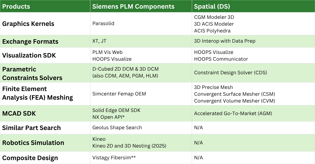
Notes:
* The NX Open API is not sold by Siemens PLM Components, but is a development kit similar to what we saw for Granite so customers can build apps on top of NX.
** Vistagy Fibersim is sold by the Specialized Engineering Solutions Group and not by Siemens PLM Components
Interestingly enough, other than the final two categories (for which Dassault has solutions in NETVIBES/ENOVIA and DELMIA respectively, just not externally licensed), the two companies stack up rather well. I find it surprising that 3DXML which DS has been promoting as a 3DEXPERIENCE exchange format doesn't show up here. In terms of overall market penetration, you'll have to read on - no spoilers!
Besides all of these proprietary kernels we have discussed, there is one open source project out there with a fascinating story: that's up next!
The Open Source kernel, Open Cascade's Fascinating History
Origins and Development

The CAD package Euclid was initially developed in the early 1970s by Jean Marc Brun and Michel Théron at the Laboratoire d’informatique pour la mécanique et les sciences de l’ingénieur (LIMSI) in France, focusing on modeling fluid flow. In 1979, they founded Datavision to commercialize their work, which was subsequently acquired by Matra, forming Matra Datavision in 1980.
Throughout the 1980s and 1990s, Matra Datavision developed the Euclid-IS solid modeling 3D CAD software, notable for its hybrid modeling approach combining boundary representation (B-rep) and constructive solid geometry (CSG) techniques.
Evolution and Open Sourcing
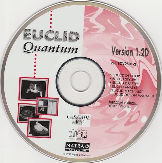
In 1997, Matra Datavision introduced EUCLID QUANTUM, a new generation of their CAD system built on the CAS.CADE (Computer Aided Software for Computer Aided Design and Engineering) platform.
By 1999, Matra Datavision transitioned CAS.CADE to open source, releasing it as Open CASCADE, which later became known as Open CASCADE Technology.
Acquisition and Legacy

In 1998, Dassault Systèmes acquired Matra Datavision, but stopped developing EUCLID, since it was redundant with the shortly-to-be-released CATIA V5, although EUCLID Styler and EUCLID Machinist survived in the CATIA V5 universe for few years until DS had absorbed the technology they could salvage from them into CATIA V5 and DELMIA V5.
Today, Open CASCADE Technology continues to be a foundational platform for various low-end CAD applications, maintained by Open Cascade Technologies (OCCT), a subsidiary of Capgemini Engineering acquired in 2014 at the end of a long series of acquisitions.
You'll see Open Cascade pop up again in this article a little later.
Solid Edge versus SolidWorks: Two Different (but similar) Paths to Parasolid
Another fascinating aspect is the parallel development of Intergraph Solid Edge and SolidWorks in the late 90s. Both companies saw the massive potential of the more powerful PCs and the Microsoft Windows NT operating system as ways of breaking into the mid-market space where UNIX machines were just simply too expensive and cumbersome. They would eventually settled on Parasolid for similar reasons, but their journeys from there reveal starkly different corporate cultures and decision-making processes.
Solid Edge: From ACIS to Parasolid

Intergraph initially launched Solid Edge with the ACIS geometric kernel, developed by Spatial Technology. However, as the product matured, Intergraph's engineering team encountered scalability and adaptability challenges that threatened the platform's future growth. This is how Bill McClure, head of Solid Edge at the time, described the situation to me:
Initially, Solid Edge faced significant performance and reliability issues with some of the key functions of the ACIS kernel. To address this, I initiated a clandestine "skunkworks" project, known only to myself and three other team members. We even rented an apartment to work in secret, away from the office. Our rapid evaluation of Parasolid quickly revealed its superior performance and reliability, solidifying our decision that we needed to switch Solid Edge to Parasolid. While the team continued to work on the Parasolid implementation offsite, I faced a challenging review meeting with the sales management team. The VP of Global Sales was highly concerned about the numerous customer and Application Engineer complaints regarding Solid Edge's modeling problems. The next day, Jim Meadlock (Intergraph CEO) demanded a solution. I revealed our secret project, explaining that our Parasolid implementation showed excellent test results. I emphasized that switching to Parasolid was crucial for our survival in the Mechanical CAD market. Jim not only endorsed the move but also suggested we broaden our discussions with Unigraphics to explore a potential joint venture. This pivotal decision ultimately led to the acquisition of Intergraph's Mechanical Software Division by Unigraphics Solutions.
This transition occurred before Unigraphics acquired Solid Edge, setting the stage for the product's integration into what would become the Siemens PLM portfolio, a fact that might be surprising to those that assumed falsely that the move to Unigraphics was responsible.
SolidWorks: Granite Denied, Parasolid Adopted

SolidWorks' kernel story reveals the sometimes-personal nature of enterprise software decisions. There was initially a prototype built on ACIS, but due to similar issues that Solid Edge has seen in their experience, they tested Parasolid as well. SolidWorks also approached PTC's CEO Dick Harrison in 1995 with a request to license PTC's proprietary geometry engine—the same geometric engine powering Pro/ENGINEER. Harrison declined to commercialize it. Mike Payne told me the story this way,
We started SolidWorks using a trial copy of ACIS, but it was full of bugs. Can you imagine a graphics kernel at the heart of your code bleeding memory like a stuck pig? I reached out to Dick [Harrison, CEO of PTC at the time] and asked him if we could license the code for the geometry engine from Pro/ENGINEER. He gave me the side-eye and said, ‘But we don’t do that, sell the engine, I mean.’ I countered, ‘That doesn’t mean you can’t start doing it now, though.’ He just stood there and after a beat said, ‘But we don’t have a model for selling it.’ So, that wasn't going to happen. As it turns out, I had already created libraries in parallel for plugging either ACIS or Parasolid into SolidWorks and found that Parasolid fixed most of our bugs and was much faster, so the decision to switch to Parasolid was easy. As time went on, Pro/ENGINEER would refuse to benchmark against us, so I guess that tells you how it worked out for SolidWorks at the end!
Harrison's refusal would prove consequential. PTC never built a model for commercializing their graphics engine because they didn't want to become an OEM for software. They preferred to focus on their core products and offer APIs for partners and customers to build on top of them (see the PTC Granite chapter above). Faced with this rejection by Dick to license the PTC graphics engine, SolidWorks signed a contract with Chuck Gridstaff at Unigraphics and adopted Parasolid, joining what would become a growing ecosystem of Parasolid-powered applications.
Author's Note: When I was working on this article and gathering these testimonials, it turns out that although Mike and Bill knew each other, they had no idea that each had struggled with simular ACIS problems (bugs and performance issues) and reached the same conclusion (they went to talk to Tony Affuso and settled on Parasolid). Both were surprised and amused when we talked about it. It is a small, weird world, the CAD/PLM world, for sure!
2025 Update: The Pattern Continues
In the opening months of 2025, ANSYS migrated SpaceClaim—originally developed by Mike Payne in 2005 and acquired by ANSYS in 2014—to theParasolid kernel, following in the footsteps of SolidWorks and Solid Edge in moving away from ACIS for improved robustness and interoperability. The product has since been rebranded as ANSYS Discovery.
The Great Divergence: Sales Strategy as Destiny
While both products shared similar technical foundations and target markets and released within a few months of each other, their sales strategies created vastly different trajectories. This divergence would ultimately determine which company would capture the larger share of the exploding mid-market CAD opportunity.
SolidWorks made a bet that would define its success: a channel-centric sales model. Rather than building a large direct sales force, the company partnered with regional resellers who could provide local support and relationships. This strategy proved remarkably effective, enabling rapid geographic expansion and customer acquisition at a fraction of the cost of direct sales.
The results were spectacular. SolidWorks' growth rate outpaced Solid Edge, establishing market momentum that would prove difficult to reverse. By 1997, just a few years after launch, SolidWorks had attracted the attention of Dassault Systèmes, which acquired the company in a deal that would transform both organizations.
In contrast, Solid Edge used a traditional direct sales model and a smaller channel model and never achieved the explosive growth that SolidWorks experienced. Its acquisition by Unigraphics (later acquired by Siemens) positioned the product within a comprehensive PLM portfolio. While it never achieved SolidWorks' market dominance, Solid Edge found its niche as part of Siemens' broader industrial software strategy, particularly in manufacturing and engineering workflows.
Cautionary Tales in CAD: When Tech Isn’t Enough
PTC's Mid-Market Misadventure: The Pro/JR Catastrophe

While Solid Edge and SolidWorks were successfully conquering the mid-market, the established high-end leader PTC was facing an uncomfortable reality: their customers were increasingly asking for more affordable alternatives to Pro/ENGINEER. PTC's response would become one of the industry's most cautionary tales.
In what can only be described as a catastrophic miscalculation, PTC launched Pro/JR in 1995—a stripped-down version of Pro/ENGINEER intended to compete with the emerging Windows-based solutions. The product was hampered by artificial limitations, poor performance, and a pricing strategy that satisfied neither high-end nor mid-market buyers.
Pro/JR's failure was so complete that it accelerated customers' migration to SolidWorks and other competitors. Rather than protecting PTC's market share, the initiative inadvertently validated the very products it was meant to compete against. The debacle reinforced PTC's eventual decision to focus exclusively on their high-end geometry engine.
In 2007, when PTC realized they needed a direct modeler for some scenarios to complement their parametric modeler, they acquired what was then CoCreate Solid Designer and rebranded it Creo Elements/Direct. This product, however, relies on a proprietary, ACIS-based kernel (see the timeline later in this article for details).
It wasn’t until 2019 that they purchased former PTCer and co-founder of SolidWorks, Jon Hirschtick’s Onshape (based on Parasolid kernel) for attacking the mid-market. I asked Steve Dertien, CTO of PTC, about whether Parasolid was still in use by Onshape:
Onshape as acquired is still based on Parasolid. That's not easy to change, but we're also not exclusive. We've already incorporated the Frustum kernel (acquired by PTC in 2018) for generative design as well as the Creo kernel for some other features. Similarly, Creo and all other CAD, do plug in other people's engines for features. For example, we don't hide that we use Materialize (from Materialize NV in Belgium) in 3D Printing or ModuleWorks (from ModuleWorks GmbH in Germany)) for CAM simulation as well as Keyshot (from Luxion Inc in Costa Mesa, CA, USA) for rendering and Ansys for simulation. Even when we added Ansys we still had to support the prior generations of simulations to maintain all the data feature compatibility. Every company decides where to build, buy and partner for technology in the stack where appropriate.
The Short, Somewhat Unhappy Life of CADDS5

CADDS5 was the final evolution of a CAD lineage dating back to CADDS1 in 1969, one of the earliest commercial drafting systems. Developed by Computervision, CADDS evolved through multiple generations — from 2D drafting to wireframe 3D (CADDS3) and eventually solid modeling (CADDS4X and CADDS5) in the 1980s. Unlike emerging kernels like Parasolid and ACIS, CADDS5 used a fully proprietary geometric modeling kernel, tightly integrated and never licensed or externalized. What made CADDS5 unique was its ability to support both direct modeling and parametric modeling, albeit via separate modules and executables — a powerful concept that prefigured later hybrid workflows.
After PTC acquired Computervision in 1998, it maintained CADDS5 for legacy industries like aerospace and shipbuilding, where long product lifecycles and regulatory lock-in made modernization difficult. But CADDS5 was eventually frozen at version 16.1 in 2013, with no future development. Its demise was due to several factors: a lack of modularity, no effort to license or replatform the kernel, and user resistance to its dated architecture and fractured modeling workflows. Meanwhile, the industry moved toward unified parametric-direct hybrid platforms like Solid Edge and, eventually, Creo.
Ironically, PTC’s later development of Creo did absorb some key lessons from CADDS5’s dual-mode modeling and large-assembly experience — but did so from a clean slate, not by reusing the CADDS kernel. The takeaway lesson is this: technological sophistication alone doesn’t ensure survival — adaptability, openness, and ecosystem strategy matter more than internal power. CADDS5 was ahead of its time in hybrid modeling but failed to evolve into an open platform others could build on. In the “kernel wars,” closed systems lost.
Forked at the Source: Autodesk’s Break from ACIS

When Autodesk set out to create Inventor—its answer to Pro/ENGINEER and SolidWorks—it knew it needed a robust 3D kernel. ACIS, then a rising player developed by Spatial Technology, was the obvious choice: proven, available, and already embedded in AutoCAD’s 3D extensions. But Autodesk made a bold move that would have long-term consequences: instead of fully committing to ACIS, they quietly forked the source code—creating their own derivative kernel called ShapeManager.
This gave Autodesk full control over the kernel’s evolution, independent of Spatial’s roadmap. But the story took a twist in late 2000, when Spatial was acquired by Dassault Systèmes, owner of SolidWorks—Autodesk’s rising nemesis. Suddenly, Autodesk found itself legally entangled with a competitor, accused of unpaid license fees on the forked code. Spatial sued. In 2003, Autodesk prevailed in court and retained royalty-free rights to its ShapeManager branch.
Meanwhile, Dassault cleaned up ACIS under Michael Payne’s leadership, fixing memory leaks and expanding functionality. But ACIS—once poised to challenge Parasolid—never regained the momentum it lost after both SolidWorks and Inventor abandoned it. While Spatial continues to license ACIS widely in mid-tier applications like BricsCAD and IronCAD, the kernel now sits behind the scenes, powering tools in markets where cost or compatibility matter more than cutting-edge modeling.
This episode isn’t just a legal footnote—it’s a striking example of kernel independence as strategic leverage. Autodesk’s decision to fork ACIS before Spatial’s acquisition gave it long-term autonomy, insulating Inventor’s roadmap from a now-rival platform. While rare, this approach has been mirrored by a few other vendors—notably CoCreate, whose SolidDesigner fork of ACIS still underpins Creo Elements/Direct. These cases serve as powerful reminders that owning your modeling core isn’t just a technical choice—it’s a business safeguard.
Today, ACIS continues to power some of the solutions of the CAD middle- and low-end markets through Spatial's OEM licensing program. Current ACIS-based applications include Dassault Systèmes' DraftSight, BricsCAD, and IronCAD (in this case they have a dual-kernel with ACIS and Parasolid) and various CAM and CMM software vendors.
From Parametric Roots to Direct Evolution: The Rise of Hybrid Modeling in CAD Kernels
While Autodesk’s decision to fork ACIS and build ShapeManager underscored the strategic value of kernel independence, it also highlighted another emerging challenge: evolving those kernels to keep pace with user expectations. As we have seen, in the early 2000s, CAD users were increasingly demanding flexibility—not just in terms of vendor lock-in, but in how they could model. The rigid, feature-driven workflows of traditional parametric CAD were giving way to a desire for more intuitive, geometry-centric interaction.
The evolution of geometric modeling in CAD has long been framed as a rivalry between two approaches: parametric modeling and direct modeling. For decades, CAD systems were architected around one or the other, each championing different priorities. But over time, these distinctions began to blur as major modeling kernels integrated support for both paradigms. Today, hybrid modeling is the norm rather than the exception.
Parametric Modeling: Constraint-Driven Precision
Parametric modeling, popularized in the 1980s and 1990s by systems like Pro/ENGINEER and CATIA V5, is built around the idea of design intent. In this approach, geometry is defined not just by shapes but by a hierarchy of features, constraints, and dimensional parameters. These parameters drive geometry updates—change a number, and the model updates predictably.
Strengths:
- Highly structured
- Reproducible and editable
- Ideal for controlled design processes (e.g. regulatory compliance, manufacturing constraints)
Limitations:
- Can be rigid and slow to edit
- Complex history trees become fragile
- Not ideal for conceptual or iterative modeling
Direct Modeling: Geometry Without Baggage
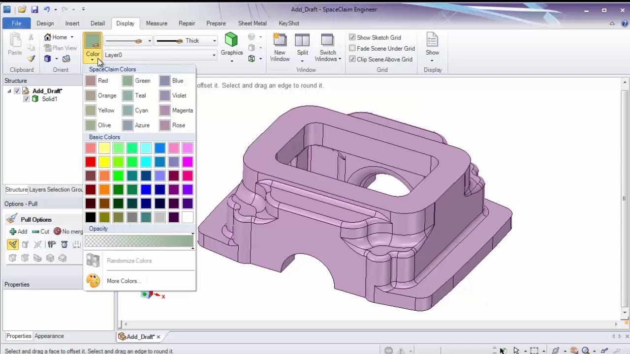
Direct modeling, by contrast, emerged in tools like CoCreate and later SpaceClaim. It allows engineers to push, pull, and reshape geometry directly without being limited by parametric constraints or feature trees. The goal is speed and flexibility—particularly useful for conceptual design, simulation prep, or editing models from external sources.
Strengths:
- Fast and intuitive
- Great for legacy data and concept work
- Excellent for multi-CAD workflows
Limitations:
- Lacks design intent unless re-parameterized
- Less predictable for controlled design revisions
The Hybrid Breakthrough: Integrating Both Worlds
As users increasingly demanded the best of both worlds, CAD vendors and kernel developers began to integrate direct editing capabilities into parametric systems, and vice versa. This was not merely a UI change—it required deep changes at the kernel level to handle both representations and allow interoperability.
Milestone 1: CATIA V5 and CGM (1999)
Dassault Systèmes' CATIA V5, released in 1999 with the CGM kernel, was among the first major platforms to enable hybrid modeling. Though its UI still leaned parametric, the underlying kernel allowed for operations that bypassed strict history-based editing. CGM supported feature-based parametric modeling while also enabling operations like Boolean edits or surface reshaping without complete regeneration.
Milestone 2: Siemens' Synchronous Technology (2008)
The breakthrough for Parasolid came in 2008 when Siemens introduced Synchronous Technology with Solid Edge ST1, followed shortly by NX 7. This innovation combined the constraint solving and feature recognition of parametric systems with the direct geometry manipulation of direct modelers, tightly integrated at the Parasolid kernel level. It allowed users to apply direct edits while preserving (or re-deriving) design intent.
Milestone 3: PTC Wildfire 5.0 and Creo Flexible Modeling (2009–2011)
PTC took a different path. Starting with Wildfire 5.0 in 2009, it introduced the Flexible Modeling Extension (FMX), a set of tools for direct editing of parametric geometry. When PTC launched Creo in 2011, FMX was fully integrated into Creo Parametric, allowing users to push and pull geometry while retaining key constraints and relationships—implemented directly in the Granite kernel.
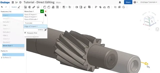
Milestone 4: Onshape and Cloud-Native Hybrid Modeling (2019)
In 2019, Onshape—a fully cloud-native CAD platform built on the Parasolid kernel—introduced its own flavor of hybrid modeling. While Onshape had supported parametric design from its inception, it added direct editing capabilities deeply integrated with its collaborative, version-controlled environment. Leveraging the flexibility of Parasolid and the scalability of the cloud, Onshape delivered hybrid modeling as a seamless, real-time experience for distributed teams.
Also in 2019, Siemens announced Convergent Modeling in their Parasolid kernel permitting both feature- and facet-based modeling at the core foundation of their modeler giving users unprecedented power over creating complex surfaces while maintaining geometric integrity.
Notable Absence: ACIS and Fragmented Support
Unlike Parasolid, CGM, or Granite, the ACIS kernel has seen more fragmented adoption of hybrid modeling. While it powers tools like BricsCAD and was once used in Inventor, few ACIS-based systems offer native support for deeply integrated parametric+direct workflows at the kernel level. Instead, hybridization—when it exists—is often handled at the application layer.
Other Players and Proprietary Paths
While the major CAD vendors rely on well-known kernels like Parasolid, CGM, and Granite, a few niche tools follow different strategies. ZW3D and VariCAD use proprietary kernels, allowing them to tightly control modeling behavior at the cost of ecosystem integration. IronCAD, uniquely, uses a dual-kernel architecture, incorporating both ACIS and Parasolid. This provides users with access to both direct and parametric tools within a single environment—albeit with some added complexity.
Conclusion: The Hybrid Kernel Era
Today, nearly every major CAD system offers hybrid modeling, but how deeply this is supported depends on kernel capabilities. The shift from "parametric vs. direct" to "parametric + direct" has redefined modeling expectations and transformed how engineers interact with 3D geometry. Far from being a mere UI convenience, hybrid modeling reflects a fundamental shift in kernel architecture, data structures, and user philosophy.
Before we talk about some of the more technological aspects of the MCAD world, let's take a detour through the mathematical underpinnings of this world!
The Computational Alchemy: How Graphics Mathematics Forged the AI Age
Boolean Operations: The Set Theory Crucible (ℝ³ → ℤ³)
Boolean operations on solids represent the first computational barrier that demanded hardware acceleration. The regularization of set operations in 3D space requires solving:
$$
S_1 \otimes S_2 = \text{closure}(\text{interior}(S_1 \star S_2))
$$
Where $\otimes$ represents regularized union/intersection/difference, and $\star$ is the standard set operator. The conversion from continuous math to discrete implementations introduces topological challenges formalized by the Jordan-Brouwer separation theorem:
$$
\partial S \text{ partitions } \mathbb{R}^3 \text{ into } \text{int}(S), \text{ext}(S), \text{ and } \partial S
$$
This theorem underpins all solid modeling kernels but requires combinatorial explosion management when implemented. For two meshes with $n$ triangles each, the intermediate intersection curve calculation has complexity:
$$
\mathcal{O}(n^{2/3} \log n + k)
$$
where $k$ is the number of intersections (Shewchuk, 1999). This mathematical reality made early CAD systems computationally prohibitive without dedicated hardware.
Bézier & NURBS: The Parametric Revolution
Bézier Geometry (Bernstein Basis)
The parametric form of Bézier curves hides profound mathematical depth:
$$
\mathbf{B}(t) = \sum_{i=0}^n \underbrace{\binom{n}{i} t^i (1-t)^{n-i}}_{\text{Bernstein polynomial}} \mathbf{P}_i
$$
The derivative reveals its connection to differential geometry:
$$
\mathbf{B}'(t) = n \sum_{i=0}^{n-1} \mathbf{\Delta P}i \cdot B{i,n-1}(t)
$$
Where $\mathbf{\Delta P}i = \mathbf{P}{i+1} - \mathbf{P}_i$. This structure enables parallel evaluation - a concept later exploited by GPU stream processors.
NURBS: Projective Geometry in Practice
NURBS introduce weights $w_i$ and knot vectors $U$ through rational parameterization:
$$
\mathbf{C}(u) = \frac{\sum_{i=0}^n N_{i,p}(u) w_i \mathbf{P}i}{\sum{i=0}^n N_{i,p}(u) w_i}
$$
The B-spline basis functions $N_{i,p}$ follow recursive evaluation:
$$
N_{i,p}(u) = \frac{u - u_i}{u_{i+p} - u_i} N_{i,p-1}(u) + \frac{u_{i+p+1} - u}{u_{i+p+1} - u_{i+1}} N_{i+1,p-1}(u)
$$
This recursion depth leads to $\mathcal{O}(p^2)$ complexity per evaluation point - a key driver for early GPU fixed-function hardware.
While parametric representations offer powerful mathematical tools for surface design, real-world engineering models often require operations on discrete mesh representations. This necessity leads us to examine the sophisticated mathematics of mesh manipulation and implicit modeling.
Mathematics of Mesh Healing, Repair, and Implicit Models
Mesh Healing and Repair: Radial Basis Functions and Parametric Mapping
Mesh healing represents a critical computational challenge in MCAD systems, addressing real-world model defects including holes, non-manifold edges, and self-intersections. The mathematical foundations of mesh repair bridge differential geometry, numerical analysis, and topology.
RBF Surface Interpolation
The Radial Basis Function approach provides a powerful mathematical framework for reconstructing surfaces from damaged meshes:
$$
s(\mathbf{x}) = \sum_{i=1}^N \lambda_i , \phi(|\mathbf{x} - \mathbf{x}_i|) + p(\mathbf{x})
$$
Where:
- $\phi(r)$ represents the radial basis function (commonly Gaussian or thin-plate spline)
- $\lambda_i$ are weights determined by solving a linear system
- $p(\mathbf{x})$ is a polynomial term ensuring affine invariance
This meshless representation enables solving the Laplace equation on the surface:
$$
\Delta u = 0 \quad \text{on the surface}
$$
The solution to this PDE creates harmonic maps that preserve geometric features while repairing topological inconsistencies - a mathematical approach that parallels the regularization techniques in modern neural networks.
Parametric Remeshing
The mathematical elegance of surface parameterization transforms mesh repair into a 2D problem:
$$
f: \mathcal{M} \subset \mathbb{R}^3 \rightarrow \Omega \subset \mathbb{R}^2
$$
This mapping minimizes distortion through energy functionals:
$$
E(f) = \int_{\mathcal{M}} |\nabla f|^2 dA
$$
The resulting parameterization enables robust triangulation algorithms that would be combinatorially intractable in 3D space - demonstrating how dimension reduction (a concept central to modern AI) originated in graphics mathematics.
Implicit Models and Meshes
Implicit modeling represents a paradigm shift from explicit mesh representation, defining surfaces as level sets:
$$
F(x, y, z) = 0
$$
This representation creates a complete partition of 3D space:
- $F(x, y, z) < 0$ (interior)
- $F(x, y, z) = 0$ (surface)
- $F(x, y, z) > 0$ (exterior)
Boolean Operations on Implicit Models
The mathematical elegance of implicit representations transforms complex Boolean operations into simple algebraic expressions:
$$
F_{A \cup B}(x, y, z) = \min(F_A(x, y, z), F_B(x, y, z))
$$
$$
F_{A \cap B}(x, y, z) = \max(F_A(x, y, z), F_B(x, y, z))
$$
$$
F_{A \setminus B}(x, y, z) = \max(F_A(x, y, z), -F_B(x, y, z))
$$
This R-function approach avoids the combinatorial explosion of mesh-based Boolean operations, providing mathematical robustness that directly influenced modern neural implicit representations.
Distance Fields and Level Sets
Signed distance fields (SDFs) represent a specialized implicit form:
$$
F(x, y, z) = \pm \min_{\mathbf{p} \in \partial \Omega} |\mathbf{x} - \mathbf{p}|
$$
The evolution of level set methods through the Hamilton-Jacobi equation:
$$
\frac{\partial \phi}{\partial t} + H(\nabla \phi) = 0
$$
This mathematical framework enables topology-changing operations that would be prohibitively complex with explicit meshes - a concept that later influenced neural network architectures for 3D shape generation.
Mesh Generation from Implicit Functions
The Marching Cubes algorithm bridges implicit and explicit representations through isosurface extraction:
$$
{\mathbf{x} \in \mathbb{R}^3 : F(\mathbf{x}) = c}
$$
This algorithm samples the scalar field on a regular grid and constructs a piecewise linear approximation of the isosurface - a discretization process mathematically analogous to the quantization operations in modern neural networks.
Having explored the mathematics of both parametric and implicit representations, we now turn to the fundamental transformations that allow these geometric entities to be positioned, oriented, and projected in three-dimensional space.
The Matrix Revolution: Homogeneous Coordinates
The 4D projective space formulation enables efficient transformations:
$$
\begin{bmatrix}
x' \ y' \ z' \ w'
\end{bmatrix}
\begin{bmatrix}
a & b & c & t_x \
d & e & f & t_y \
g & h & i & t_z \
0 & 0 & 0 & 1
\end{bmatrix}
\begin{bmatrix}
x \ y \ z \ 1
\end{bmatrix}
$$
But the true power emerges in composition:
$$
\mathbf{M}{\text{total}} = \mathbf{M}{\text{proj}} \cdot \mathbf{M}{\text{view}} \cdot \mathbf{M}{\text{model}}
$$
Matrix concatenation follows the Thompson group structure, requiring 4x4 matrix multiplication at 60+ FPS - a task impossible for 1990s CPUs but ideal for GPU parallelization.
Rendering Equations: Light as Integrals
The path from Phong shading to ray tracing rests on solving the rendering equation (Kajiya, 1986):
$$
L_o(\mathbf{x}, \omega_o) = L_e(\mathbf{x}, \omega_o) + \int_{\Omega} f_r(\omega_i, \omega_o) L_i(\mathbf{x}, \omega_i) (\mathbf{n} \cdot \omega_i) d\omega_i
$$
Monte Carlo integration transforms this into:
$$
L_o \approx \frac{1}{N} \sum_{k=1}^N \frac{f_r L_i (\mathbf{n} \cdot \omega_{i_k})}{p(\omega_{i_k})}
$$
With variance reduction requiring importance sampling:
$$
p(\omega_i) \propto f_r(\omega_i, \omega_o) (\mathbf{n} \cdot \omega_i)
$$
This mathematical structure directly inspired importance sampling in variational autoencoders and modern denoising techniques.
GPU Architecture: Mathematics Made Silicon
The computational patterns forced GPU designers to create:
- SIMT Architecture: Single Instruction Multiple Thread
- Hierarchical Memory: Registers → Shared → L1/L2 → Global
- Tensor Cores: Mixed-precision matrix units
Compare graphics and AI workloads:
| Operation | Graphics | AI |
|---|---|---|
| Matrix Multiply | View/projection transforms | Neural network layers |
| Reduction | Z-buffer depth test | Loss calculation |
| Filtering | Texture sampling | Attention mechanisms |
The AI Symbiosis: From Polygons to Parameters
The mathematical throughline becomes clear:
| Graphics Kernel | AI Operation |
|---|---|
| Vertex shader matrix transforms | Neural network layer $Wx + b$ |
| Texture filtering | Convolutional neural networks |
| Marching cubes isosurfacing | Decision boundary visualization |
| Monte Carlo ray tracing | Bayesian neural networks |
| Photon mapping | Particle filter methods |
The 2012 AlexNet breakthrough used 2.9 million CUDA cores (NVIDIA GTX 580) - hardware originally designed for graphics math.
Quantum Connections: Hilbert Space Meets Vertex Shaders
The mathematical tools developed for graphics find new life in quantum computing:
- Qubit State Visualization: Uses Marching Cubes algorithm
- Quantum Circuit Simulation: Leverages sparse matrix ops from FEM
- Quantum Machine Learning: Uses GPU-accelerated tensor networks
The density matrix formulation:
$$
\rho = \sum_i p_i |\psi_i\rangle \langle\psi_i|
$$
Requires the same Hermitian inner product calculations as BRDF lobe sampling.
Conclusion: The Unbroken Mathematical Chain
From the Boolean algebra of CSG to the tensor cores in modern GPUs, the mathematical demands of computer graphics created:
- Hardware Architectures for massive parallelism
- Numerical Libraries for matrix/tensor operations
- Algorithmic Paradigms for approximate integration
These became the foundation for:
- Transformer models ($\mathcal{O}(n^2)$ attention matrices)
- Physics-informed neural networks (PDE discretization)
- Quantum computing simulations (Kronecker products)
The $500 billion AI industry rests on mathematical frameworks forged in the CAD labs of the 1970s. Every forward pass in a neural network, every quantum circuit simulation, and every photorealistic render traces its lineage to these fundamental graphics mathematics - proving that the virtual worlds we built to design cars and airplanes ultimately became the blueprint for machine intelligence.
Sources
The Evolution of Surfacing Technologies — People, Companies, and the Creative Machines Behind the Magic
Equally important in the evolution of the Kernel Wars, the battle for controlling surfaces - and ultimately the automotive body industry as well as the nascent Hollywood Special Effects industry, is the history of surfacing technology. It is not only a tale of mathematical innovation—it is one of brilliant individuals, storied companies, and groundbreaking applications that have shaped everything from cars and aircraft to Hollywood creatures. Behind each curve and smooth surface lies a lineage of ambition and sometimes failure that fueled the digital design revolution.
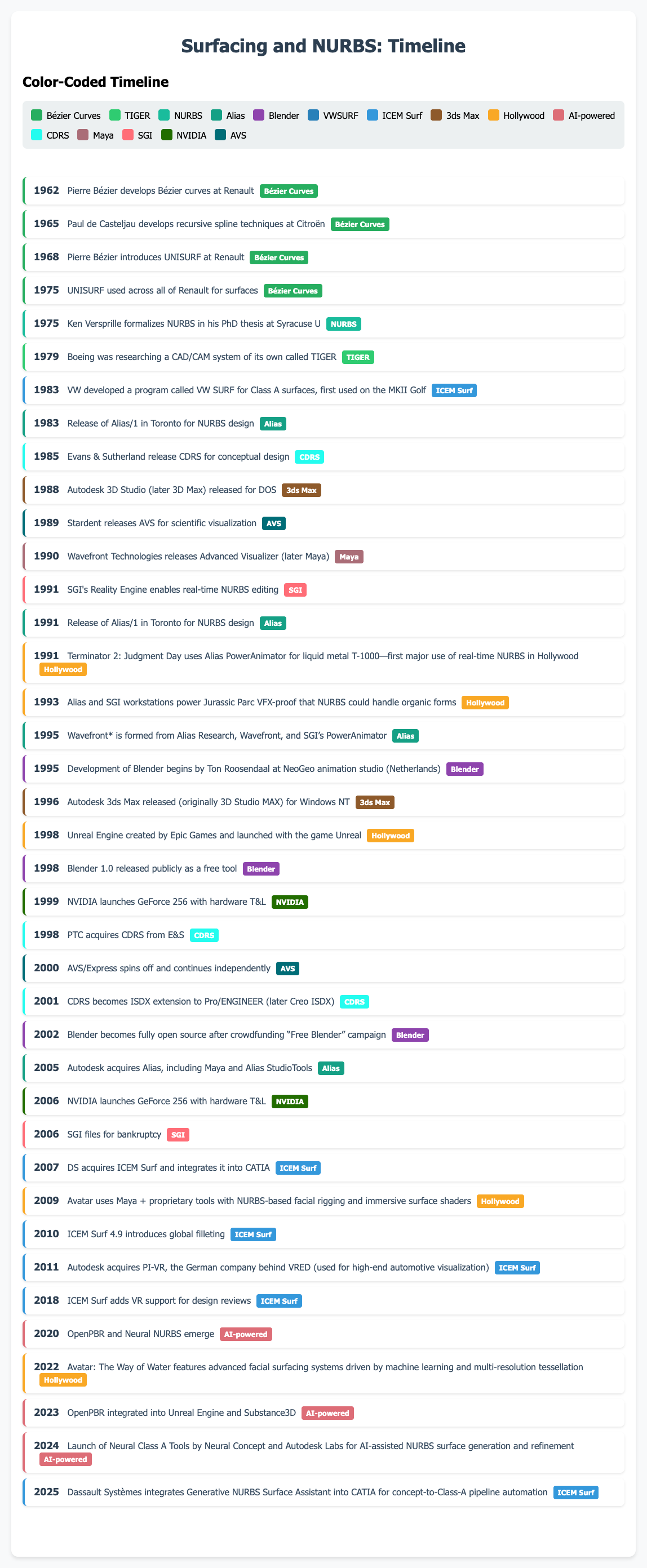
The Pioneers of Curves: Bézier, de Casteljau, and Versprille
Pierre Bézier, an engineer at Renault in the 1960s, developed what we now call Bézier curves and surfaces. They provided designers with a way to manipulate complex shapes intuitively, long before interactive 3D CAD existed. Paul de Casteljau at Citroën simultaneously explored similar curve systems using recursive algorithms—his work laid the mathematical foundation, while Bézier’s name became the standard.
In the 1970s, Dr. Ken Versprille, then a PhD student at Syracuse University, extended these ideas into NURBS (Non-Uniform Rational B-Splines). His insight: with rational weights and local control, NURBS could represent both conic sections and freeform shapes. This was the key that made them invaluable in both engineering and animation.
Volkswagen, Control Data, and the Birth of ICEM Surf
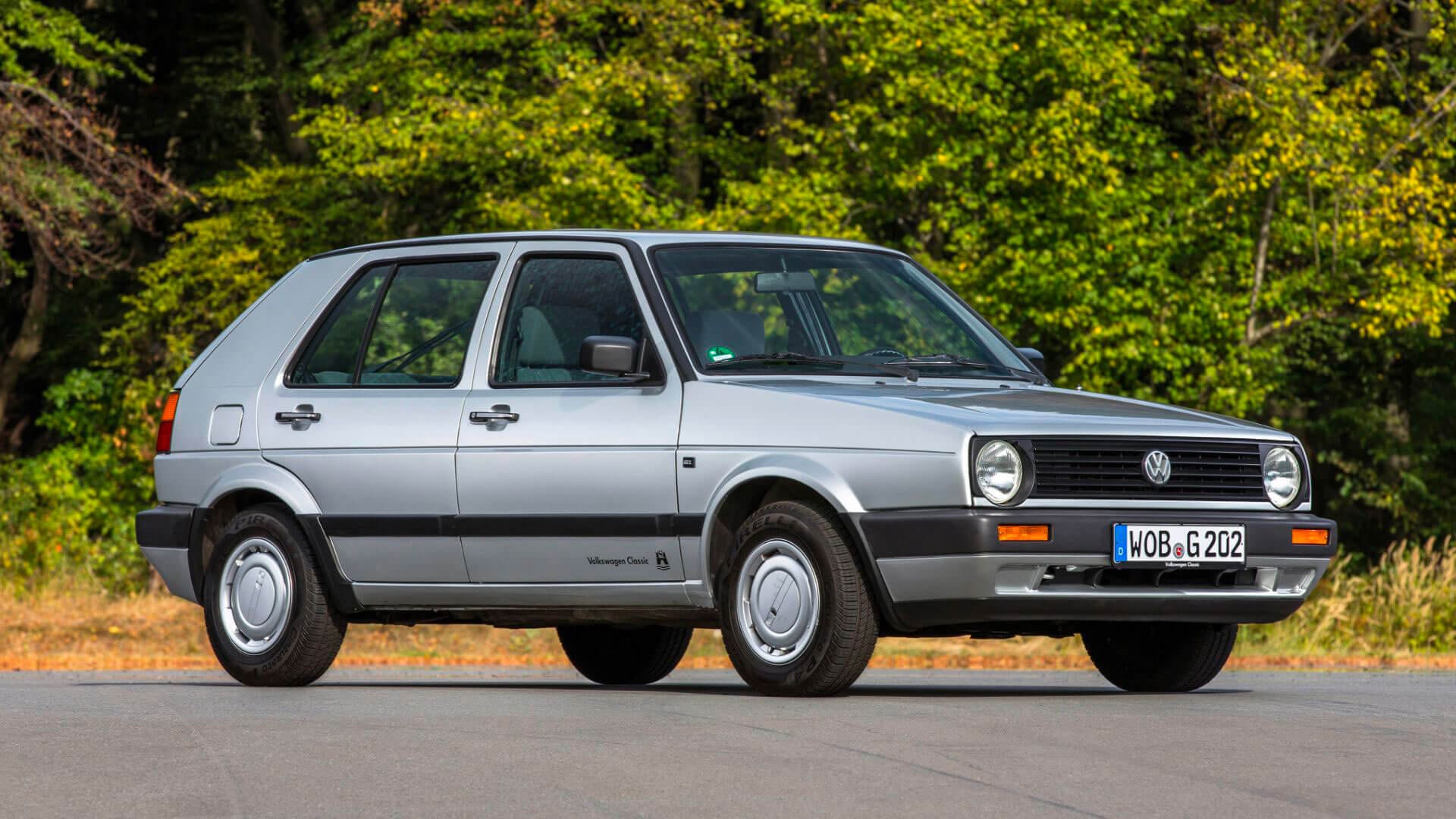
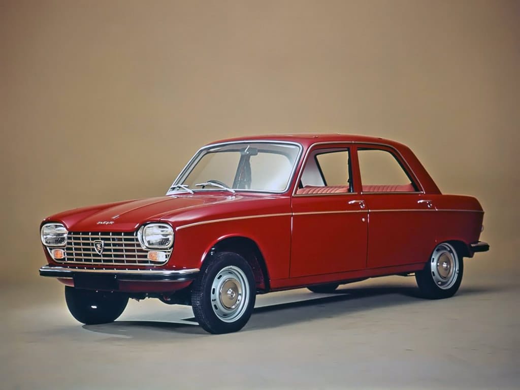
Volkswagen, looking to design sleeker cars in the late 1970s, developed VWSurf in partnership with Control Data Systems. This was later commercialized as ICEMsurf, which quickly became the industry standard for “Class A” surfaces—those demanding high aesthetic and manufacturability standards.
ICEM Surf’s rise was shaped by its success on European luxury vehicles like the VW Golf and Ford Taurus, and later by brands like BMW and Porsche. The software focused on high-end surfacing quality and real-time reflection analysis, which was pivotal for luxury and sports car design. In 2007, Dassault Systèmes acquired ICEM Surf, integrating it into CATIA V5 as “CATIA ICEM Shape Design.”
The Canadian and Californian Contenders: Alias and CDRS

In 1983, a Toronto-based team launched Alias/1, which brought real-time NURBS to SGI workstations. Alias soon became essential in industrial design and animation. Used to model everything from the Mazda RX-7 to the dinosaurs in Jurassic Park, Alias was eventually acquired by Autodesk in 2006 and remains a key product in automotive design.
Simultaneously, Evans & Sutherland developed CDRS (Conceptual Design and Rendering System), used extensively by Chrysler and other manufacturers. CDRS focused on ergonomic conceptual modeling and later inspired key elements of PTC’s early surfacing modules.
Stardent’s Dissolution and AVS’s Legacy
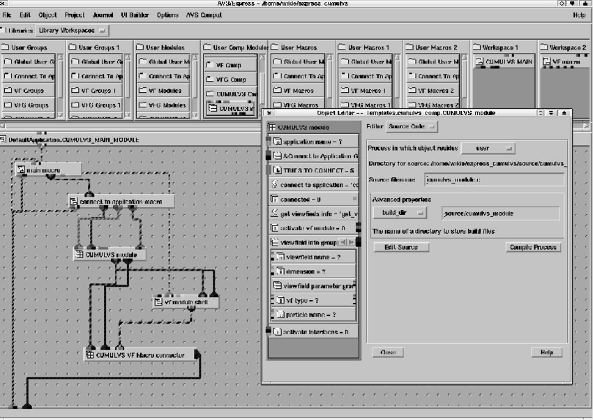
Meanwhile in Toronto, Stardent, born from a merger between Ardent and Stellar, created AVS for scientific surface rendering. AVS evolved into AVS/Express, used in molecular and geophysical visualization. It was notable for its integration of visual workflow for creating graphics images. It lives on at avs.com as an innovative data visualization toolkit, but competes with open-source platforms like VTK and ParaView.
Beyond the Obvious: Modern Surfacing Excellence
Some of the finest examples of modern surfacing aren’t defined by gimmicks or media hype, but by their mastery of curvature continuity, light reflection, and manufacturability:
- Lucid Air: Designed with Alias and CATIA, its aerodynamic surfaces and subtle detailing reflect true Class A modeling.
- Rimac Nevera: This Croatian electric hypercar features intricate airflow channels, modeled with a blend of ICEM Surf and VR-based review tools.
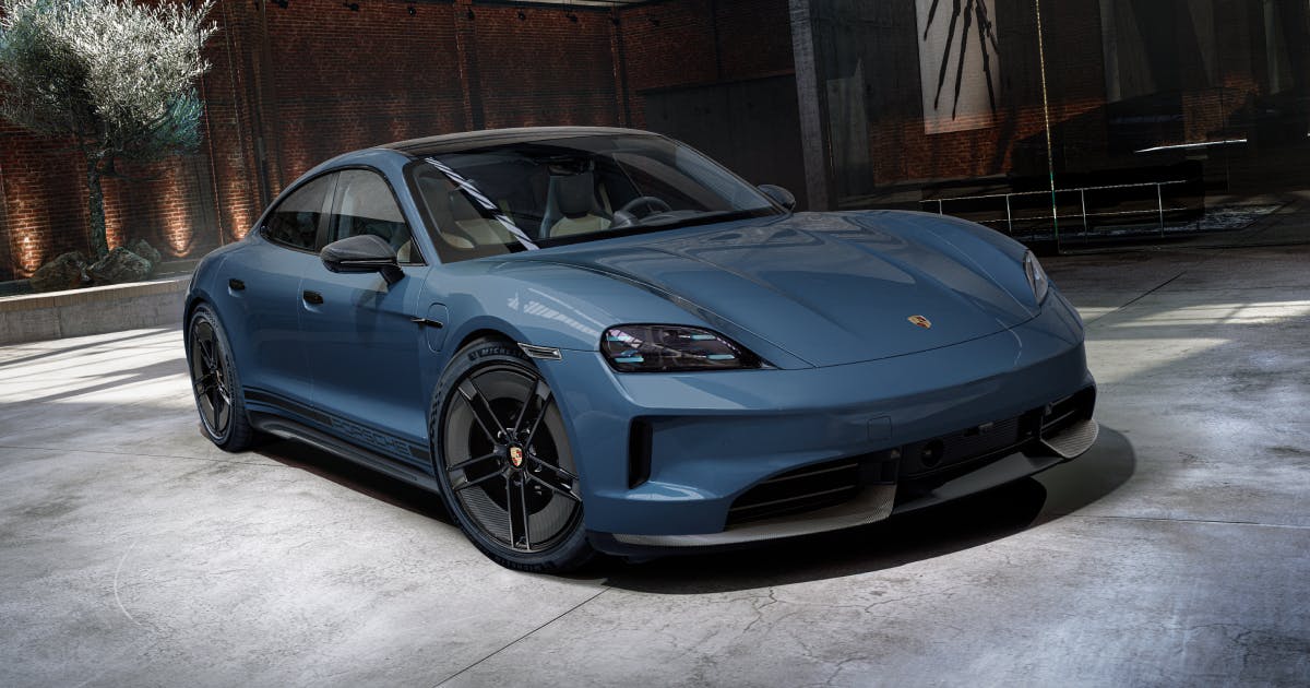
- Porsche Taycan: Leveraging Dassault’s surfacing tools, it shows advanced continuity in curvature across fenders, doors, and spoilers.
These vehicles highlight how modern surfacing software is about more than looks—it’s about aerodynamics, manufacturability, and brand language.
From NURBS to Neural: Surfacing in the Age of AI
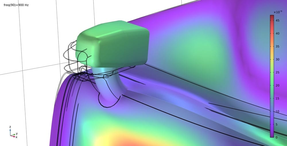
The 2020s have brought a new generation of surfacing tools. Neural NURBS, powered by machine learning, suggest optimal control point layouts for a designer’s intent. Adaptive Mesh Refinement now tailors tessellation in real-time. Open standards like OpenPBR ensure that materials look consistent across rendering platforms, from Substance 3D to Unreal Engine 6.
Even holographic modeling is emerging, with companies like Neural Concept pioneering tools that blend topology optimization, AR/VR visualization, and surface continuity.
The frontier now lies not in manual control, but in intelligent delegation. The question has shifted from Can we model this? to What’s the smartest way to model this—collaboratively, precisely, and in real time?
The Evolution of Graphics APIs
Graphics APIs have been the unsung heroes of the Kernel Wars, serving as the critical bridge between surfacing algorithms and visual output. These interfaces translated mathematical constructs like Bézier surfaces and NURBS into renderable forms, powering CAD, visual effects, and scientific visualization. The evolution of graphics APIs reflects a fierce battle among industry giants—IBM, HP Labs, Sun Microsystems, and Silicon Graphics (SGI)—each vying to define the standard for 3D rendering. This chapter explores how APIs shaped surfacing technologies, from early standards like PHIGS to OpenGL’s dominance and the rise of modern low-level APIs, while highlighting the vendor rivalries that drove innovation.
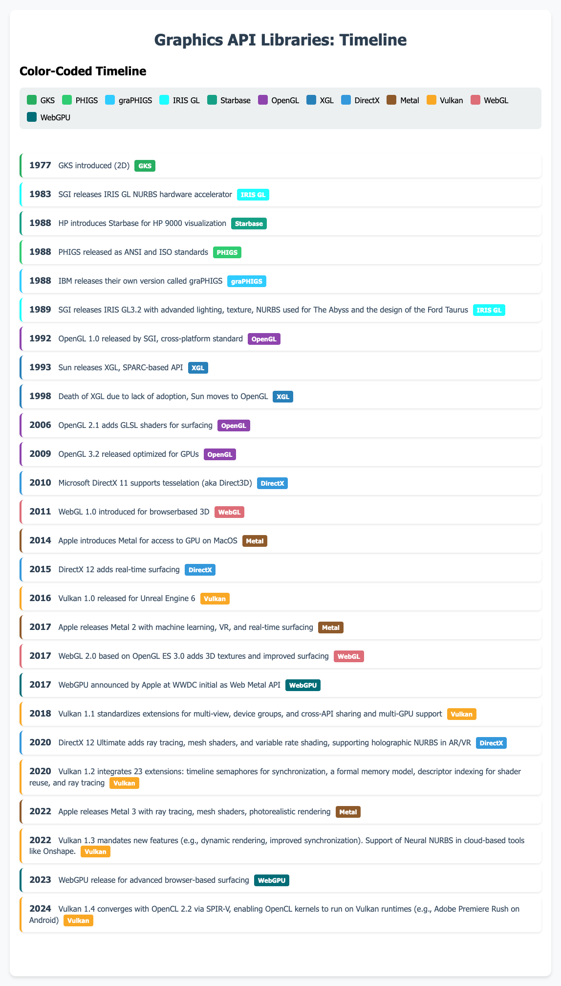
Early Standards: GKS, PHIGS, and graPHIGS
The roots of graphics APIs trace back to the 1970s with the Graphical Kernel System (GKS), an ISO standard for 2D graphics adopted by IBM and HP for early CAD systems. GKS provided a device-independent framework but lacked robust 3D capabilities, limiting its use for complex surfacing. By the 1980s, PHIGS (Programmer’s Hierarchical Interactive Graphics System) emerged as a 3D successor, offering a hierarchical structure for managing complex models. IBM’s graPHIGS, a high-performance implementation of PHIGS, ran on mainframes like the IBM 3090 and UNIX workstations, supporting Bézier and NURBS surfaces in early CATIA and CDRS workflows. graPHIGS was optimized for CAD but suffered from rigidity and slow performance in real-time applications, making it less suited for emerging VFX needs.
IBM pushed graPHIGS aggressively, leveraging its mainframe dominance to integrate it into engineering workflows at companies like Boeing. Meanwhile, HP Labs developed its own PHIGS-based solutions for the HP 9000 series, focusing on scientific visualization for oil and gas industries. Sun Microsystems, a rising UNIX workstation vendor, adopted PHIGS for its SPARCstations but prioritized portability over performance, lagging behind IBM’s optimized implementations. SGI, however, took a different path with its proprietary IRIS GL, introduced in 1983 for IRIS workstations. IRIS GL’s hardware-accelerated rendering of NURBS surfaces, used in Alias/1, gave SGI an edge in automotive and VFX markets, setting the stage for a fierce API standards war.
The Rise of OpenGL and Vendor Rivalries
In 1992, SGI transformed the landscape by releasing OpenGL, a cross-platform API derived from IRIS GL. OpenGL’s flexibility, hardware acceleration, and vendor-neutral governance under the OpenGL Architecture Review Board (ARB) made it the de facto standard for CAD, VFX, and games. Supporting Alias/1, Maya, and ICEM Surf, OpenGL enabled precise rendering of NURBS surfaces on diverse platforms, from SGI’s Onyx to HP’s Visualize workstations. Its open nature outpaced proprietary APIs like graPHIGS, which IBM struggled to adapt to commodity hardware.
The 1980s and 1990s saw intense competition. IBM, banking on graPHIGS, invested heavily in its RS/6000 workstations, targeting aerospace and automotive CAD. HP Labs countered with Starbase, a proprietary API for HP 9000 systems, optimized for scientific visualization but less versatile than OpenGL. Sun’s XGL, introduced in 1993, aimed to compete with OpenGL but was tied to Sun’s SPARC hardware, limiting adoption. SGI’s dominance in high-end graphics, fueled by OpenGL and its Geometry Engine, made it the preferred platform for Hollywood VFX (*Jurassic Park*, 1993) and automotive design (Ford Taurus). However, SGI’s reliance on proprietary hardware left it vulnerable as NVIDIA’s GPUs and OpenGL’s portability shifted the market to PCs.
The 2009 release of OpenGL 3.2 introduced the Core Profile, removing deprecated features and optimizing for modern GPUs like NVIDIA’s GeForce series. This update enhanced complex surface rendering for ICEM Surf and CATIA on commodity hardware, further eroding the need for specialized workstations. OpenGL’s cross-platform support also enabled Maya to run on Windows and Linux, democratizing access to high-quality surfacing.
Successors and Modern APIs
By the 2010s, OpenGL faced challenges from Microsoft’s Direct3D, which dominated PC gaming with DirectX 9–11. Direct3D’s tight integration with Windows and support for NURBS tessellation in DirectX 11 (2010) made it a viable alternative for CAD and VFX. Apple’s Metal API (2014), designed for macOS and iOS, optimized GPU performance for surfacing in tools like Autodesk Flame, though its platform exclusivity limited adoption. The Khronos Group’s Vulkan (2016) addressed OpenGL’s inefficiencies, offering low-level GPU access for real-time surfacing. Vulkan’s efficiency powers Unreal Engine 6’s holographic NURBS, enabling AR/VR design for Meta’s Horizon Worlds.
WebGL (2011), based on OpenGL ES, brought surfacing to browsers, enabling cloud-based CAD platforms like Onshape. WebGPU (2023), a successor to WebGL, further enhanced browser-based rendering, supporting AI-driven surfacing for medical visualization. These modern APIs integrate with Neural NURBS and Adaptive Mesh Refinement (AMR), enhancing Hollywood VFX (*Tomb Raider II*, 2025) and real-time surgical simulations. However, the shift to low-level APIs like Vulkan and DirectX 12 (2015) has increased developer complexity, sparking debates over accessibility versus performance.
Vendor Battles and Industry Impact
The API wars were as much about vendor strategy as technology. IBM’s graPHIGS faltered as its RS/6000 line lost ground to PCs, and by the late 1990s, IBM shifted focus to software like CATIA. HP’s Starbase faded as OpenGL became ubiquitous, though HP’s workstations adopted OpenGL for CAD. Sun’s XGL and SunGL (a partial OpenGL implementation) failed to gain traction, contributing to Sun’s decline before its 2010 acquisition by Oracle. As we mentioned before, SGI’s OpenGL success was bittersweet; while it standardized 3D graphics, NVIDIA’s CUDA and commodity GPUs rendered SGI’s hardware obsolete, leading to its 2006 bankruptcy.
Graphics APIs have been pivotal in surfacing’s evolution. PHIGS and graPHIGS enabled early CAD, OpenGL democratized high-quality rendering, and Vulkan and WebGPU support cutting-edge applications. These APIs have shaped industries by enabling precise, real-time visualization, from automotive Class A surfacing to medical imaging, while vendor rivalries drove innovation and disruption.
How MCAD and Computer Graphics Drove Each Other: A Story of Mutual Acceleration
Before we wrap up the Kernel Wars, I thought it would be good to look at the hardware side of the trench warfare fought between companies we discussed such as Silicon Graphics. Here is the story of graphics adapters and AI, their unlikely beneficiary of the 21st century!
The Early Days: From Drafting Desks to Digital Dreams
In the 1960s, engineers and designers still hunched over drafting tables, painstakingly drawing blueprints by hand. The arrival of computers promised to change everything, but early systems were massive, expensive, and limited to simple calculations. The breakthrough came with Ivan Sutherland’s Sketchpad at MIT—a system that let users draw directly on a screen with a light pen, laying the foundation for interactive computer graphics and modern CAD[2]. This was the first spark: MCAD (Mechanical Computer-Aided Design) demanded better graphical interfaces, and computer graphics responded.
1970s–1980s: The Feedback Loop Begins
As industries like automotive and aerospace pushed for more complex designs, MCAD software evolved from simple 2D drafting to 3D surface and solid modeling[2]. This leap required computers that could handle not just lines and circles, but complex curves, surfaces, and eventually, full assemblies. The need for real-time visualization of these models drove demand for more powerful graphics hardware.
- Technical Breakthroughs:
- Bézier and B-spline curves (by Pierre Bézier at Renault and others) enabled the precise mathematical modeling of car bodies and airplane wings.
- The development of hidden surface algorithms and shading models (Gouraud, Phong, Blinn) allowed MCAD users to see realistic renderings, not just wireframes.
MCAD’s hunger for better visualization fueled the rise of UNIX workstations from companies like SGI, Sun, and HP. These machines, equipped with specialized graphics hardware, became the backbone of design studios and engineering departments.
The Rise and Fall of SGI — A Decade of 3D Hardware Glory
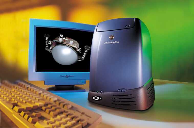
Founded in 1981 by Jim Clark, Silicon Graphics, Inc. (SGI) created groundbreaking 3D workstations and graphics subsystems that defined high-end visualization throughout the 1980s and 1990s. SGI workstations powered Alias, CATIA, and Maya, enabling VFX for films like Terminator 2, Jurassic Park, and The Abyss. Their custom MIPS processors, advanced geometry engines, IRIS GL (which later evolved into OpenGL), and high-performance visualization systems like the Onyx and RealityEngine set standards in rendering performance and visual realism.
SGI’s IRIX operating system enabled sophisticated memory and compute optimization specifically for visual simulation. From aerospace and weather simulation to molecular modeling and automotive design, SGI became synonymous with technical visualization. Their machines, though costly, were unmatched.
However, SGI’s failure to pivot to commodity hardware and general-purpose computing on GPUs was its undoing. As x86 PCs grew more powerful and flexible, SGI’s proprietary hardware lost its edge. The arrival of NVIDIA’s GeForce 256 (1999) with hardware transform and lighting, and especially CUDA (2006) for general-purpose GPU computing, meant that SGI’s once-unassailable market became obsolete. SGI filed for bankruptcy in 2006, capping off a dramatic rise and fall.
The 1990s: Democratization and Acceleration
The introduction of affordable PCs and graphics accelerators (like the 3Dfx Voodoo and NVIDIA’s early cards) meant that MCAD was no longer confined to elite workstations. Software like AutoCAD, CATIA, and Pro/ENGINEER began to leverage these new graphics capabilities, enabling complex assemblies and parametric modeling on desktop computers.
- Technical Leap: NVIDIA’s GeForce 256 (1999) integrated transform and lighting engines, making real-time 3D manipulation of MCAD models possible for a much wider audience. This was a game-changer: engineers could now rotate, zoom, and edit large assemblies interactively, dramatically speeding up design cycles.
Mistakes and Missed Opportunities
- As we discussed earlier, SGI and other workstation vendors failed to adapt to the commoditization of graphics hardware, clinging to proprietary systems as PCs and GPUs rapidly improved.
- Early MCAD software was often tied to specific hardware, making transitions to new platforms painful and slowing adoption. Companies like SolidWorks jumped on the Windows NT bandwagon and gained a massive competitive advantage!
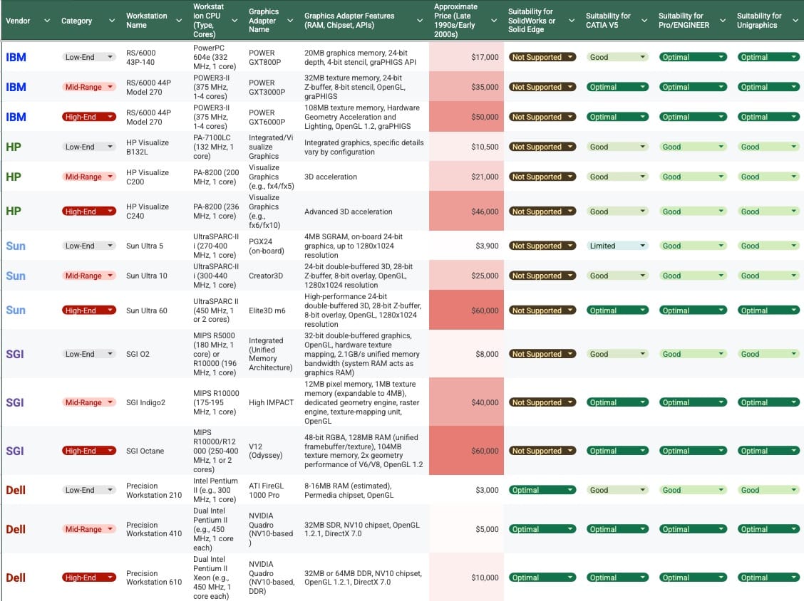
Just to give you an idea of the disconnect in market pricing between the UNIX workstations and the nascent Windows PC in the late 90s, here is a handy (but long, sorry) table for study:
2000s–Today: The GPU Revolution and AI
- As GPUs became programmable, MCAD software started using them not just for rendering, but for simulation—finite element analysis, fluid dynamics, and more. NVIDIA’s CUDA platform enabled MCAD vendors to offload heavy computations to the GPU, vastly accelerating tasks like stress analysis and generative design.
- Crucially, the relentless pursuit of real-time 3D fidelity and complex simulation within MCAD was a primary driver for the creation and rapid evolution of the Graphics Processing Unit (GPU) in the 1990s. This specialized hardware, initially designed to meet CAD's insatiable hunger for visual and computational power, has since found its ultimate and most impactful application in the 2020s, becoming the foundational engine for the Artificial Intelligence revolution.
Today, MCAD runs on everything from cloud servers to iPads and Macs, using APIs like Metal (Apple), DirectX (Microsoft), and Vulkan. Apple’s custom silicon (M-series chips) integrates powerful GPUs, allowing engineers to manipulate complex assemblies on mobile devices with the same ease as on desktops. Every leap in MCAD demanded a leap in graphics hardware—and every breakthrough in computer graphics unlocked new possibilities for design. From the first light pen sketches to today’s AI-driven generative design, the partnership between MCAD and computer graphics has been a relentless, mutually accelerating race.
The Kernel Wars: A Modern Perspective
Today's CAD landscape is defined by a complex ecosystem of geometric kernels and constraint solvers, each representing different strategic approaches. To better understand it, let's first look at the history of the various platforms:
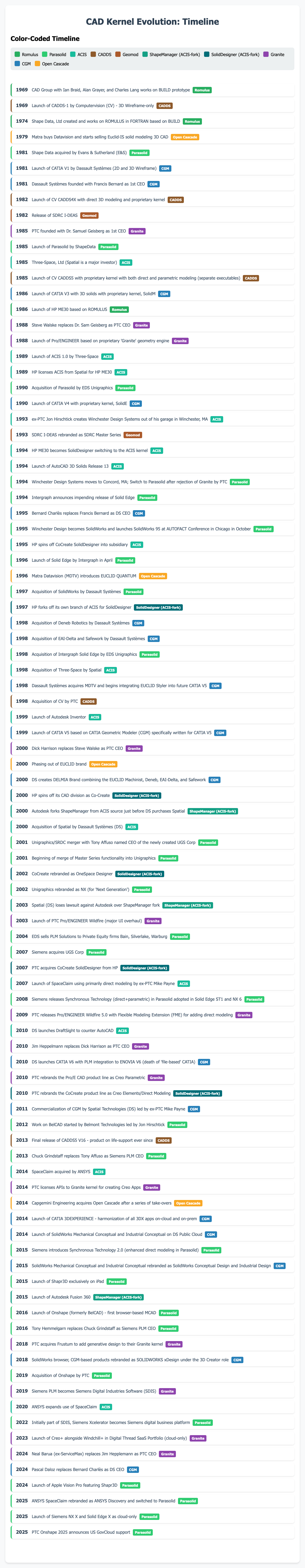
Fun fact: I was born in 1969 at the same time as BUILD :-)
Now, let's look at some characteristics of the primary graphics engines:

Notes:
- Parametric: Controls geometry using parameters and constraints that can be edited later.
- Direct: Allows users to push, pull, or drag geometry without relying on a history tree.
- Surface & Solid Modeling: Engine can manage complex solids and mathematical surfaces
- Hybrid Mesh-BREP Support: Integrates faceted mesh data with solid boundary representation in a unified model.
- History/Feature Tree: Records and organizes modeling steps in a sequential, editable timeline.
In summary,
- Parasolid = Interoperability king, especially for mainstream CAD; licensed externally by Siemens PLM Components
- ACIS = Flexible, easier to license, good for lightweight CAD/CAM; licensed externally by Spatial Technologies (DS)
- CGM = High-end kernel with deep integration in CATIA; licensed externally by Spatial Technologies (DS)
- Granite = Tight coupling with Creo. The APIs for building apps on top of it were made licensable under the newly baptized name "Granite" in 2014 for building apps on top of Creo
The following table illustrates the current state (2025) of this competitive landscape:

Of note in the table above, SpaceClaim was created by Mike Payne after SolidWorks and Spatial and it used ACIS until 2024; ANSYS recently announced that the latest version of SpaceClaim now uses Parasolid instead and was rebranded as ANSYS Discovery in 2025.
We already mentioned the Spatial lawsuit in the Autodesk chapter due to their forking of ShapeManager off of the ACIS source tree. CoCreate also forked their SolidDesigner kernel off of the ACIS source tree at around the same time as the Spatial takeover, but I found no evidence of a lawsuit in this case. That product lives after a few acquisitions as PTC Creo Elements/Direct and as far as I could determine, it still uses this proprietary fork of ACIS code.
This ecosystem reveals several interesting patterns:
- Parasolid dominance: Powers the widest range of applications, from high-end NX to emerging tools like Shapr3D
- ACIS is still hanging on: Particularly for smaller CAD packages that are competing directly in the B2C market with AutoCAD
- Strategic ironies: SolidWorks (Dassault) and Onshape (PTC) both use Siemens Parasolid technology
- Dassault and PTC both use three different graphics kernels in their MCAD portfolios.
Now, let's look at the estimated marketshare at the high-end:

We can see that Dassault's CATIA has a dominant position (~46%) with their powerful CGM kernel, followed by Parasolid, Granite and a few others.
Now, if we look at the mid-market (paid) solutions,

We see DS SolidWorks in a commanding position of about 40% market share followed by Autodesk, Siemens and PTC. ACIS has an almost negligible marketshare because of the predominance of the two forked solutions.
Finally, if we just look for the number of seats mixing all markets together and finding a winner, we find:

Parasolid, due to its many adopters. has about a 45% market share, followed by ShapeManager, CGM, and the others.
Lessons from the Battlefield
The history of all these graphics kernels and software companies offer several enduring lessons for technology companies:
- Geographic clustering drives innovation. The concentration of geometric modeling expertise in Cambridge, UK, stemming from foundational work like the Romulus kernel, created a center of excellence that continues to influence the global CAD industry.
- Kernel decisions have long-term consequences. The early choices about geometric modeling engines continue to influence these products decades later, with the Cambridge-developed foundations still powering much of today's CAD industry.
- Listening to customers can be a game-changer. As we saw in the history of CATIA V5, the tight collaboration between the very exigent Toyota engineers and the DS labs produced one of the most powerful and dominant high-end kernels ever, CGM.
- Distribution can trump technology. Despite comparable technical capabilities, SolidWorks' channel strategy enabled faster market penetration than Solid Edge's approach, while PTC's Pro/JR demonstrated how poor positioning can destroy even established brand advantages.
- Technological sophistication alone doesn’t ensure survival — adaptability, openness, and ecosystem strategy matter more than internal power as illustrated by the history of Computervision, CADDS5, and SGI.
- Openness can be a virtue as exemplified by Parasolid’s dominance in the licensed kernel market while still powering fiercely competitive in-house products like Siemens NX, Solid Edge, and now Siemens NX X.
- Corporate strategy shapes product destiny. Both Solid Edge and SolidWorks succeeded, but within very different strategic contexts, while PTC's mid-market misstep reinforced their high-end focus.
- Timing matters, but execution matters more. Both companies recognized the Windows opportunity simultaneously, but SolidWorks' superior reseller channel execution proved decisive.
Conclusion
The Kernel Wars have played a pivotal role in shaping the landscape of CAD software. From the early days of Romulus to the development of ACIS, CGM, Granite, and ultimately Parasolid, the choices made by various vendors have had lasting impacts on the industry. The journeys of Solid Edge and SolidWorks, while fascinating, are just two examples of how strategic decisions about geometric kernels can influence product development, market positioning, and competitive dynamics.
The ironies of the Kernel Wars are numerous. Dassault Systèmes, the owner of SolidWorks, pays royalties to Siemens for using Parasolid, while Siemens licenses technology from Dassault for some of their products. PTC also licenses Parasolid for some of their products (Creo Elements and Onshape). These interdependencies highlight the complex and often ironic nature of the CAD industry.
Ultimately, the Kernel Wars underscore the importance of timing, execution, and strategic decision-making in the world of CAD software. The concentration of geometric modeling expertise in Cambridge, the distribution strategies of SolidWorks, and the long-term consequences of early kernel choices all serve as valuable lessons for the industry. As we look to the future, the legacy of the Kernel Wars will continue to shape the evolution of CAD technology and the competitive landscape of the industry.
Notes:
- David Weisberg's excellent History of CAD book available on the Shapr3D website:
https://www.shapr3d.com/blog/history-of-cad - Another great resource on CAD history with a focus on Unigraphics/NX: https://www.computer.org/csdl/magazine/an/2024/04/10679561/20b3j9K7tMA
- Initial lawsuit brought by Spatial (DS) against Autodesk for their ShapeManager branch of ACIS (the lawsuit was lost by Spatial in 2003): https://www.wsgr.com/publications/PDFSearch/autodesk0306.pdf
- Verdict of Spatial versus Autodesk trial: https://www.wsgr.com/publications/PDFSearch/SpatialvAutodesk.pdf
- Great article on the history of NURBS and surfacing:
- Switch of SpaceClaim kernel from ACIS to Parasolid and its rebranding as ANSYS Discovery:
https://ansyshelp.ansys.com/public/account/secured?returnurl=///Views/Secured/corp/v251/en/sc_releasenotes/spc_advisories.html - Technical white paper about Siemens Synchronous Technology:
https://www.plm.automation.siemens.com/legacy/docs/Synchronous_Technology_CPDA_WhitePaper.pdf - Launch of PTC Creo APIs for Creo Apps: https://support.ptc.com/images/cs/articles/2020/06/1593411762dEcH/PTC_Creo_Granite_Interoperability_Kernel._Final.pdf?utm_source=chatgpt.com
- Engineering.com article comparing Parametric and Direct modeling:
https://www.engineering.com/whats-the-difference-between-parametric-and-direct-modeling/ - A good chronology of CAD in French:
http://5axes.free.fr/chronologie.html - MCAD Milestones | Minneapolis College of Art and Design https://www.mcad.edu/why-mcad/mcad-milestones
- History of CAD software - Wikipedia https://en.wikipedia.org/wiki/History_of_CAD_software
- Computer graphics - Wikipedia https://en.wikipedia.org/wiki/Computer_graphics
- Another good CAD history:
https://scispace.com/pdf/the-future-and-the-evolution-of-cad-fulznz14x9.pdf - The Evolution of Computer Graphic Design https://www.hongkongda.com/the-evolution-of-computer-graphic-design/
- AMD GPU: History of Computer Graphics - geekom https://www.geekom.au/advanced-micro-devices-amd-a-history-of-computer-
- Computer Graphics and Animation – a Critical history https://raewyn-turner.squarespace.com/s/HIS2e07.pdf
- History of Computer animation - Timeline - Historydraft https://historydraft.com/story/computer-animation/timeline/714
- The late, great Dr. Ken Versprille and his story of the invention of NURBS:

MCAD Milestones | Minneapolis College of Art and Design https://www.mcad.edu/why-mcad/mcad-milestones
History of CAD software - Wikipedia https://en.wikipedia.org/wiki/History_of_CAD_software
Computer graphics - Wikipedia https://en.wikipedia.org/wiki/Computer_graphics
The Evolution of Computer Graphic Design https://www.hongkongda.com/the-evolution-of-computer-graphic-design/
AMD GPU: History of Computer Graphics - geekom https://www.geekom.au/advanced-micro-devices-amd-a-history-of-computer-
Computer Graphics and Animation – a Critical history https://raewyn-turner.squarespace.com/s/HIS2e07.pdf
History of Computer animation - Timeline - Historydraft https://historydraft.com/story/computer-animation/timeline/714
- GKS Wikipedia
- PHIGS Wikipedia
- IBM graPHIGS Documentation
- OpenGL Wikipedia
- OpenGL 3.2 Specification
- Vulkan Wikipedia
- Microsoft DirectX Documentation
- Apple Metal Documentation
- Silicon Graphics Wikipedia
- The Rise and Fall of Silicon Graphics
- NVIDIA CUDA Wikipedia
- WebGL Wikipedia
- WebGPU Specification
- WebGPU Chrome Release
- Sun XGL Documentation
- Stanford GSB, IBM’s Adaptation
PS. Many thanks to Jacques Leveillé Nizerolle, Alain Dugousset, Michael Payne, Bill McClure, tony affuso, Akos Kapui, Evan Knuttila, Jon Hirschtick, and Steve Dertien who gave me invaluable insights into the early days of CGM, CATIA V5, SolidWorks, Spatial, Solid Edge, Parasolid, Shapr3D, Granite, Onshape, and Creo.