Overview of Product Development in a PLM/Engineering Context
Definition and Scope
Product development is the process of creating new products or improving existing ones through a systematic approach that integrates various engineering disciplines and leverages technology to optimize design, manufacturing, and lifecycle management. In the context of Product Lifecycle Management (PLM) and engineering, product development encompasses strategies, methodologies, tools, and processes aimed at enhancing innovation, reducing time-to-market, and ensuring compliance with quality standards.
Historical Context
The evolution of product development has been profoundly influenced by technological advancements in CAD (Computer-Aided Design), CAM (Computer-Aided Manufacturing), and CAE (Computer-Aided Engineering). These technologies have progressively integrated into the engineering workflow, enabling more efficient design, analysis, and manufacturing processes. Historically, manual methods were predominant, which limited iterative cycles and complex simulations. The advent of digital tools has significantly streamlined these processes.
Key Concepts
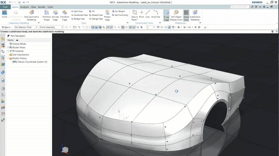
- CAD: Central to product development, CAD software enables engineers to create detailed 2D and 3D designs using graphical representations.
- CAM: Focuses on automating the manufacturing process through computerized machine control systems, ensuring precise fabrication based on CAD-generated models.
- CAE: Involves simulations and analyses (like structural analysis, thermal analysis) to validate design before physical prototyping or production.
- PLM: Manages all aspects of a product’s lifecycle from concept to end-of-life, integrating data, processes, people, and systems.
Current Trends
-
Digital Twin Technology: This involves creating virtual representations of physical products to simulate performance and optimize designs in real-time. It is increasingly integrated with IoT (Internet of Things) for enhanced monitoring and predictive maintenance.
-
Additive Manufacturing: A rapid prototyping technique that uses 3D printing, enabling faster development cycles and customization.
-
AI/ML Integration: Artificial intelligence and machine learning are being applied to predict outcomes, optimize processes, and enhance decision-making in the product development lifecycle.
-
Sustainability Focus: Emphasis on eco-friendly materials, energy efficiency, and circular economy principles is driving changes in design and manufacturing practices.
Relevance to PLM Practitioners
For PLM practitioners, understanding the role of CAD, CAM, CAE, and digital technologies within the broader context of product development is crucial. Mastery of these tools enhances their ability to manage complex projects efficiently, ensuring seamless integration across various stages of product lifecycle management. Effective use of PLM systems can streamline data flow, reduce errors, and improve communication among cross-functional teams.
In summary, the landscape of product development is continuously evolving with new technologies and methodologies. For PLM practitioners, keeping abreast of these advancements ensures that they remain at the forefront of innovation and efficiency in their respective fields.