Overview of CAD/CAM in the Context of PLM/Engineering
Definition and Historical Background
CAD (Computer-Aided Design) and CAM (Computer-Aided Manufacturing) are integral components within the broader field of Product Lifecycle Management (PLM). Historically, these technologies emerged to enhance the efficiency and accuracy of design and manufacturing processes. CAD facilitates the creation, modification, analysis, and documentation of designs through graphical models, while CAM automates the conversion of a designed product's geometry into precise instructions for machines that manufacture it.
Key Concepts
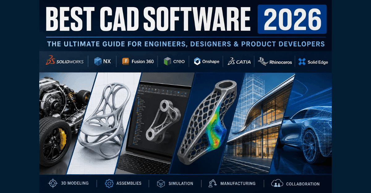
CAD:
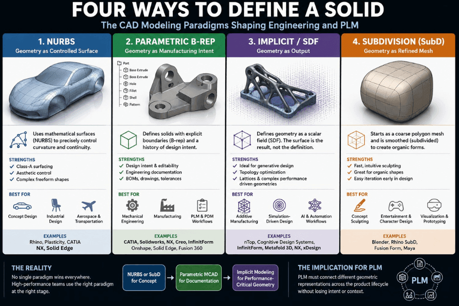
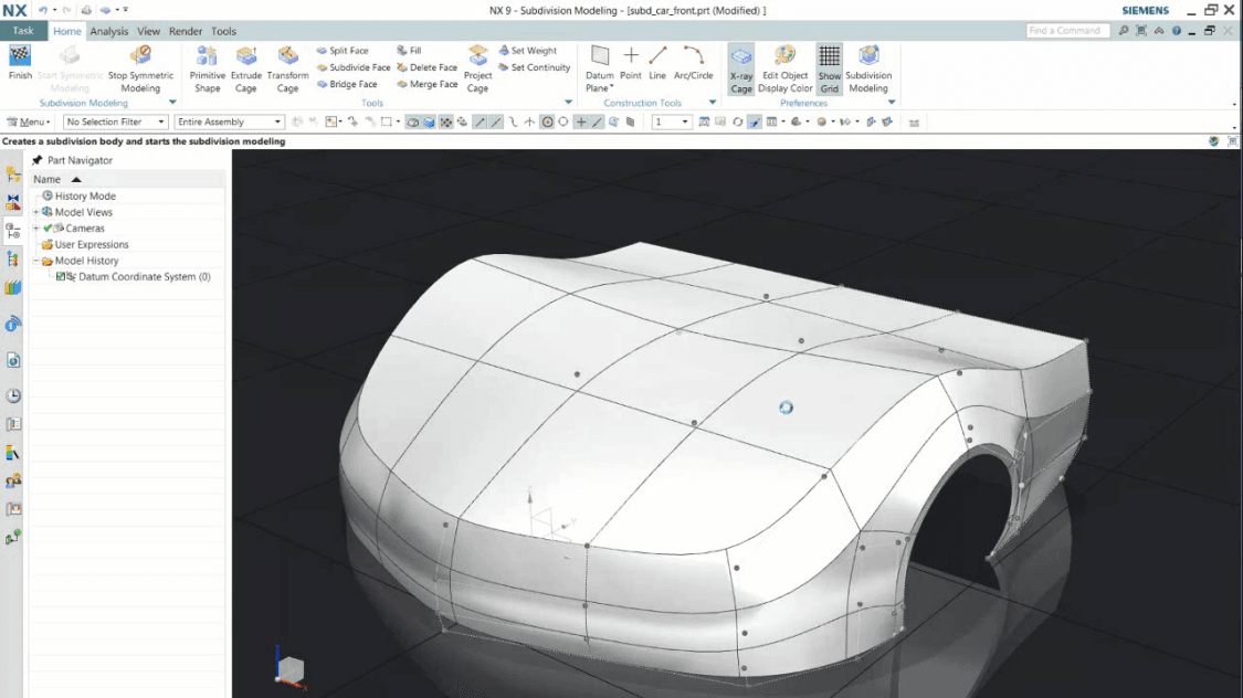
- Design Process: CAD software allows engineers to create detailed 2D drawings or 3D models. This process is iterative, enabling real-time adjustments and visualization.
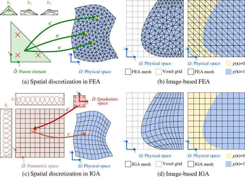
- Simulation Capabilities: Some advanced CAD systems include finite element analysis (FEA) for structural integrity testing, thermal simulations, and other critical analyses.
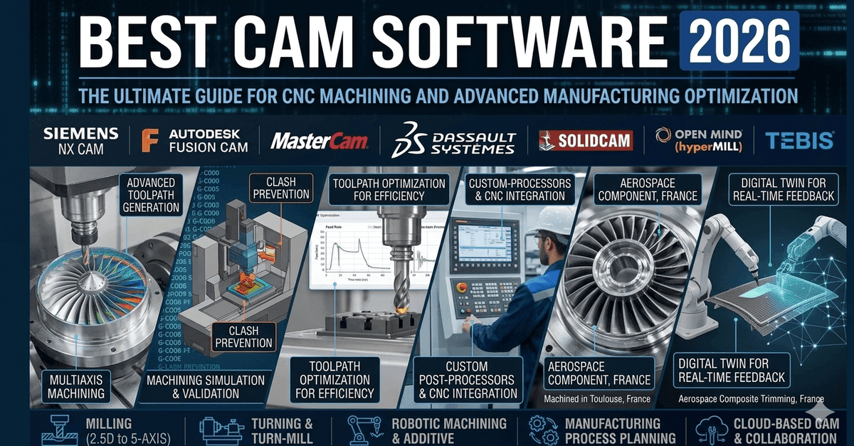
CAM:
- Toolpath Generation: CAM software translates design specifications into toolpaths—sequences of motions that machines follow to create parts or components. This includes milling, turning, welding, and more.
- Automation: Automation in manufacturing processes can reduce errors and increase productivity through the precise execution of machine operations.
Current Trends
-
Integration with PLM:
- CAD/CAM systems are increasingly integrated into broader PLM solutions to ensure seamless data flow throughout the product lifecycle. This integration supports real-time updates, version control, and collaboration among teams.
-
Additive Manufacturing (3D Printing):
- The rise of 3D printing has necessitated advancements in both CAD (for creating printable models) and CAM (to generate build paths for printers).
-
Artificial Intelligence (AI) and Machine Learning:
- AI can optimize design processes by predicting outcomes based on historical data, automating repetitive tasks, and enhancing decision-making.
- Machine learning algorithms are used to refine toolpaths, predict machine performance, and improve overall manufacturing efficiency.
Relevance to PLM Practitioners
For professionals in the field of PLM and engineering, understanding CAD/CAM is crucial for several reasons:
- Efficiency: By optimizing design and manufacturing processes, practitioners can reduce development time and costs.
- Quality Control: Advanced tools allow for detailed analysis and validation before production, ensuring high-quality end products.
- Data Management: Integration with PLM systems helps in managing complex data workflows, maintaining consistency across all stages of the product lifecycle.
- Innovation: With continuous advancements in CAD/CAM technologies, engineers can explore new design possibilities and manufacturing techniques.
Conclusion
CAD and CAM are indispensable tools for modern engineering and PLM practices. Their evolution towards greater integration and advanced features is reshaping how products are designed and manufactured. As such, staying informed about the latest trends and applications of these technologies is essential for professionals aiming to drive innovation and efficiency in their work.