Overview of Geometry Kernels in PLM/Engineering Context
Definition
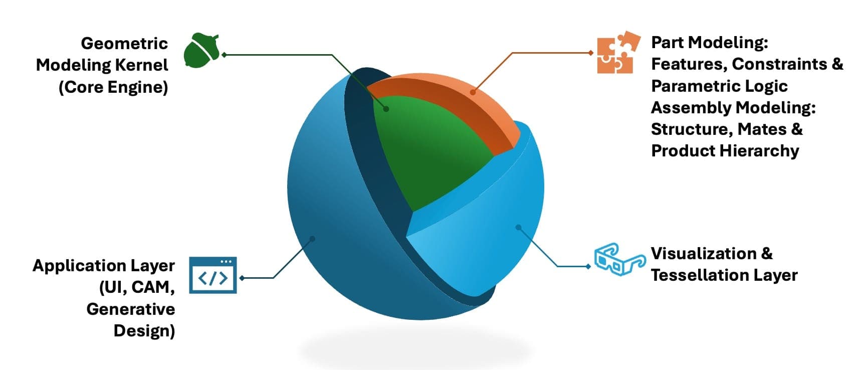
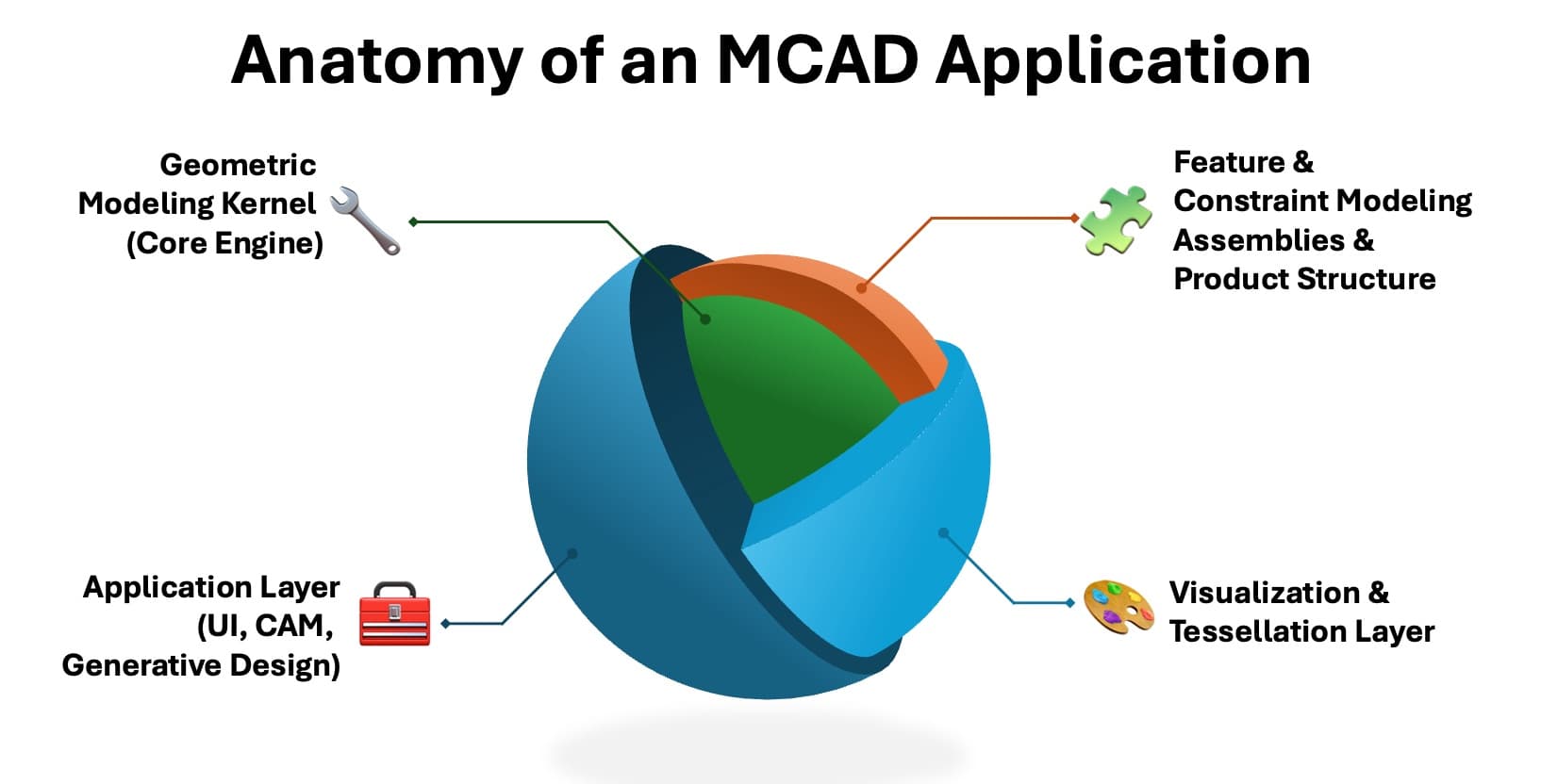
Geometry kernels are the core components within Computer-Aided Design (CAD) software that handle the geometric modeling and manipulation of 3D objects. These kernels provide the fundamental functions required to create, edit, analyze, and optimize complex shapes and structures. They operate at a low-level abstraction, managing tasks such as surface definition, solid modeling, mesh generation, and other critical operations necessary for product lifecycle management (PLM).
History
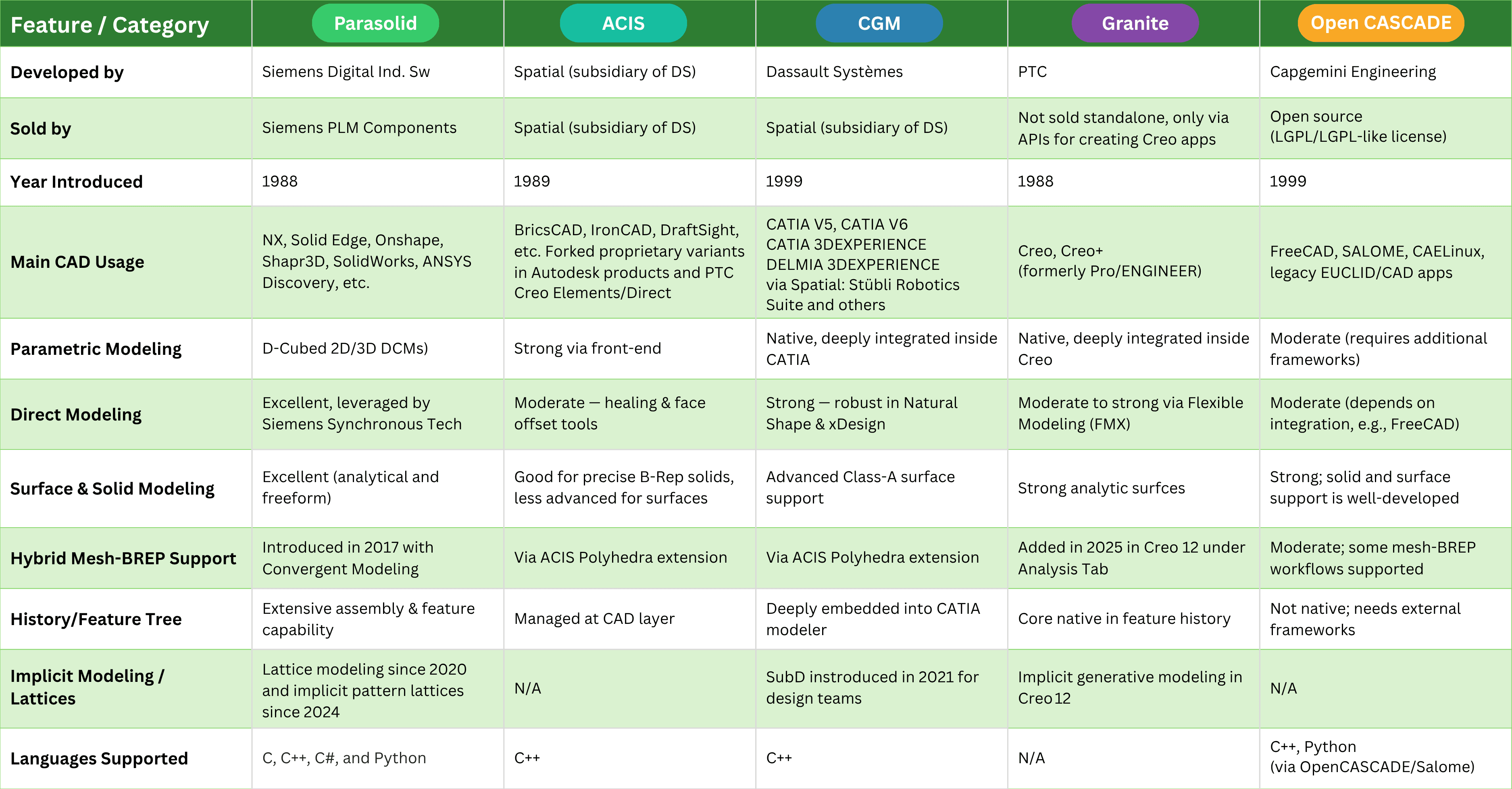
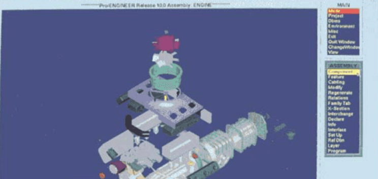
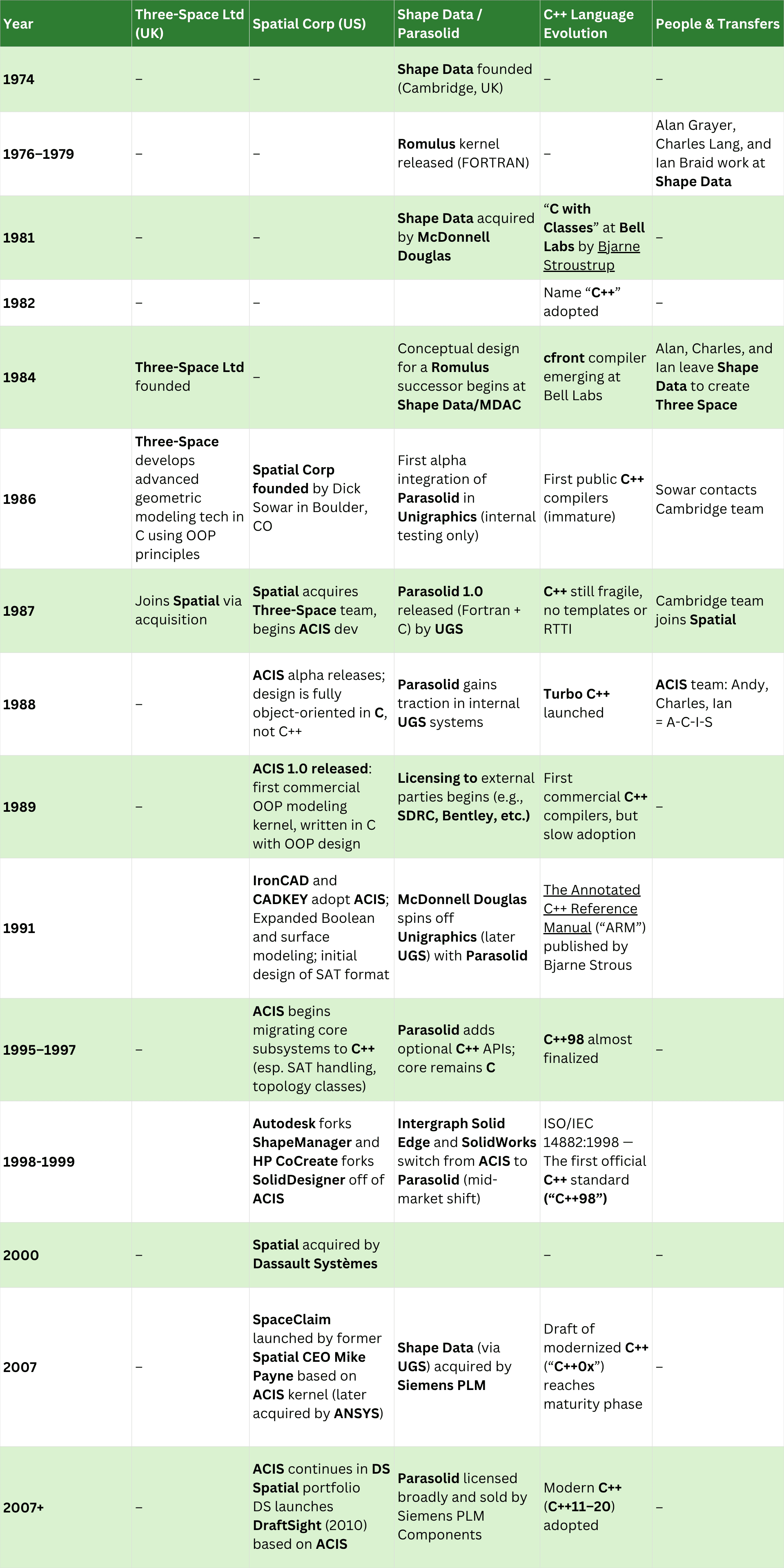
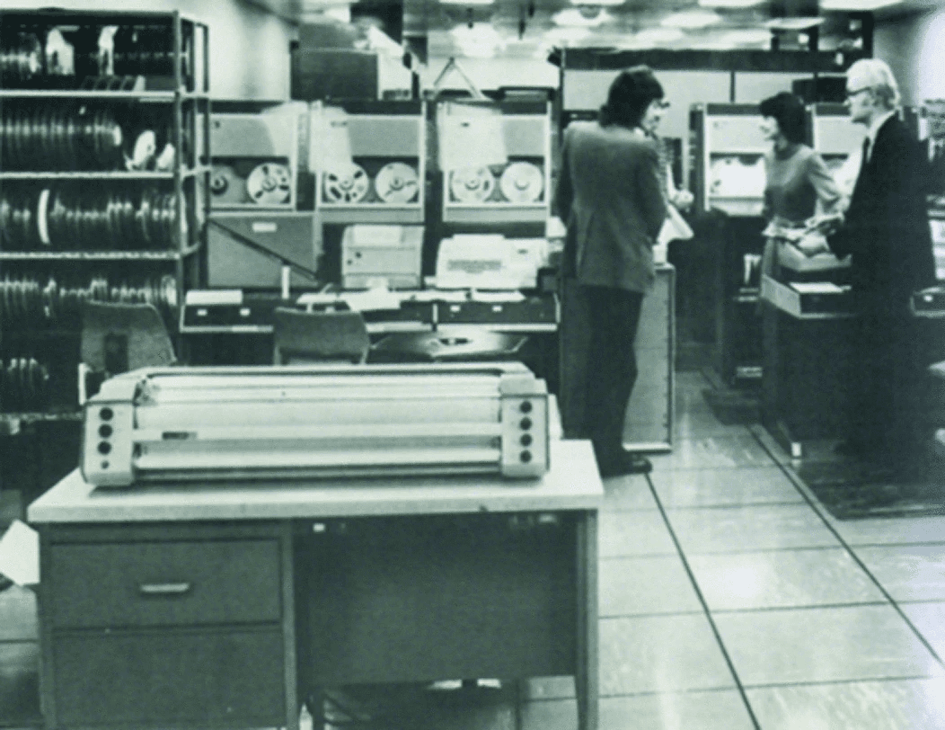
The evolution of geometry kernels has paralleled advancements in computational technology and engineering needs. Early CAD systems relied on simple wireframe models, which were limited to 2D representations. The introduction of parametric and feature-based design methods during the late 1980s and early 1990s marked a significant shift towards more complex solid modeling capabilities. This era saw the development of several influential geometry kernels like Parasolid, ACIS (Intergraph), and SolidWorks Kernel, which provided robust support for real-world engineering applications.
Key Concepts
- Topology: The study of geometric relationships such as connectivity, adjacency, and boundaries.
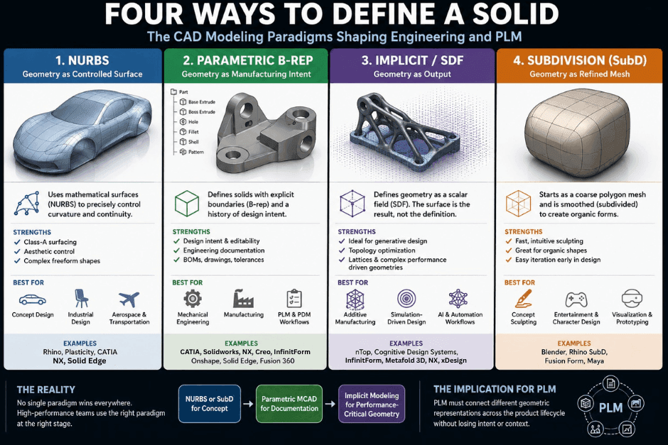
- Geometry Representation: Methods to describe shapes using points, lines, surfaces, and solids.
- Boolean Operations: Functions like union, intersection, and subtraction used to create new objects from existing ones.
- Surface Modeling: Techniques for creating smooth, continuous surfaces that can represent complex engineering designs.
- Parameterization: The use of mathematical functions to define geometric shapes in a controlled manner.
Current Trends
In recent years, there has been a significant push towards integrating advanced computational geometry techniques into CAD kernels. Key trends include:
- High-Fidelity Modeling: Enhanced support for high-resolution and real-time rendering capabilities.
- Integrated Simulation Tools: Combining geometry kernels with finite element analysis (FEA) and other simulation tools to enable predictive design.
- Collaborative Design Environments: Development of cloud-based platforms that allow multiple users to work on the same model simultaneously, leveraging distributed computing resources.
- AI and Machine Learning Integration: Utilizing machine learning algorithms for intelligent modeling, optimization, and anomaly detection in geometric designs.
Relevance to PLM Practitioners
Geometry kernels play a crucial role in Product Lifecycle Management (PLM) by providing the foundation for efficient design processes. For practitioners, understanding these tools is essential for several reasons:
- Model Integrity: Ensuring that designs remain accurate and consistent throughout the development process.
- Collaboration: Facilitating seamless interoperability across different departments and teams using various CAD systems.
- Optimization: Leveraging advanced modeling techniques to reduce material usage, improve performance, and enhance overall product quality.
- Compliance: Supporting regulatory compliance by enabling precise and reproducible design documentation.
In conclusion, geometry kernels are indispensable components in modern PLM/Engineering environments. As technology continues to evolve, the integration of sophisticated geometric processing capabilities will further enhance the efficiency and innovation potential in product development processes.